Code No. P0158: Left Bank Oxygen Sensor (Rear) Circuit High Voltage
OPERATION
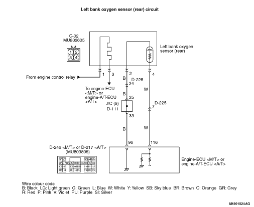
- The sensor signal is inputted to the engine-ECU <M/T>
or engine-A/T-ECU <A/T> (terminal No. 116) from the left bank oxygen sensor (rear) output
terminal (terminal No. 4).
- The left bank oxygen sensor (rear) (terminal No. 2) is earthed with engine-ECU <M/T>
or engine-A/T-ECU <A/T> (terminal No. 96).
FUNCTION
- The left bank oxygen sensor (rear) converts the concentration
of oxygen in the exhaust emission into a voltage and inputs the signal to the engine-ECU <M/T>
or engine-A/T-ECU <A/T>.
- When the air-fuel ratio is richer than the theoretical air-fuel ratio, the left
bank oxygen sensor (rear) outputs a voltage of about 1 V. When it is leaner than the theoretical
air-fuel ratio, it outputs a voltage of about 0 V.
- In response to the signal, the engine-ECU <M/T> or engine-A/T-ECU <A/T>
controls the fuel injection amount so that the air-fuel ratio can be equivalent to the theoretical
air-fuel ratio.
TROUBLE JUDGMENT
Check Condition
- Above 2 seconds later after the engine has started up.
- Left bank oxygen sensor (rear) output voltage is 1.2 V or more for 2 seconds.
PROBABLE CAUSES
- Short circuit in left bank oxygen sensor (rear) circuit
or loose connector contact
- Failed engine-ECU <M/T> or engine-A/T-ECU <A/T>
DIAGNOSIS PROCEDURE |
STEP 1. M.U.T.-III data list |
|
Q.
Is the check result normal?
|
 Intermittent malfunction (Refer to GROUP 00 - How to Use Troubleshooting/Inspection
Service Points - How to Cope with Intermittent Malfunctions Intermittent malfunction (Refer to GROUP 00 - How to Use Troubleshooting/Inspection
Service Points - How to Cope with Intermittent Malfunctions  ). ). |
|
 Go to Step 2 . Go to Step 2 . |
|
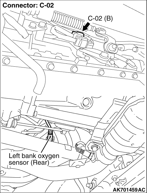
STEP 2. Connector check: C-02 left bank oxygen sensor (rear) connector |
Q.
Is the check result normal?
|
| Go to Step 3 . |
|
| Repair or replace the connector. |
|
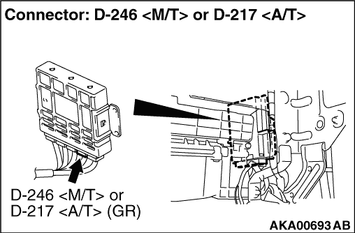
STEP 3. Connector check: D-246 engine-ECU <M/T> connector or D-217 engine-A/T-ECU <A/T> connector |
Q.
Is the check result normal?
|
| Go to Step 4 . |
|
| Repair or replace the connector. |
|
STEP 4. Check harness between C-02 (terminal No. 4) left bank oxygen sensor (rear) connector and D-246 (terminal No. 116) engine-ECU <M/T> connector or D-217 (terminal No. 116) engine-A/T-ECU <A/T> connector. |
|
|
Q.
Is the check result normal?
|
| Go to Step 5 . |
|
| Repair the damaged harness wire. |
|
STEP 5. Check harness between C-02 (terminal No. 2) left bank oxygen sensor (rear) connector and D-246 (terminal No. 96) engine-ECU <M/T> connector or D-217 (terminal No. 96) engine-A/T-ECU <A/T> connector. |
|
|
Q.
Is the check result normal?
|
| Go to Step 6 . |
|
| Repair the damaged harness wire. |
|
STEP 6. M.U.T.-III data list |
|
Q.
Is the check result normal?
|
| Intermittent malfunction (Refer to GROUP 00 - How to Use Troubleshooting/Inspection
Service Points - How to Cope with Intermittent Malfunctions ). |
|
| Replace the engine-ECU <M/T> or engine-A/T-ECU <A/T>. |
|