Code No. P0628: Suction Control Valve Open <Euro3, Euro4>


OPERATION
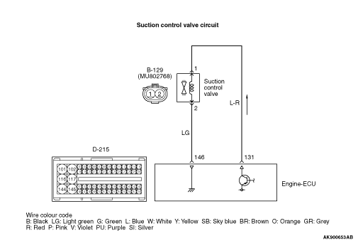
- The current is applied from the engine-ECU (terminal No. 131) to the suction
control valve (terminal No. 1) and earthed to the engine-ECU (terminal No. 146) from the suction
control valve (terminal No. 2).
FUNCTION
- The engine-ECU performs duty control over the suction control valve.
- The engine-ECU checks whether the amount of current for driving duty is adequate.
TROUBLE JUDGMENT
Check Conditions
- Battery positive voltage is 8 - 16 V
- 2 seconds later after the ignition switch has been in "ON" position or the engine
has started up.
- The supply pump and injector are being normally controlled.
- The fuel injection amount is 4 mm3/st or more.
- When the driving duty ratio of the suction control valve is higher than the specified
value, the driving current is lower than the specified value.
PROBABLE CAUSES
- Failed suction control valve
- Open circuit or harness damage in suction control valve circuit or loose connector
contact
- Failed engine-ECU
DIAGNOSIS PROCEDURE |
STEP 1. Connector check: B-129 suction control valve connector |
Q.
Is the check result normal?
|
 Go to Step 2 . Go to Step 2 . |
|
 Repair or replace the connector. Repair or replace the connector. |
|
STEP 2. Check suction control valve itself. |
|
Q.
Is the check result normal?
|
| Go to Step 3 . |
|
Replace the suction control valve. After replacing the suction control valve,
learn the supply pump (Refer to GROUP 00 - Precautions Before Service - What
The Common Rail Engine Learns  ). ). |
|
STEP 3. Connector check: D-215 engine-ECU connector. |
Q.
Is the check result normal?
|
| Go to Step 4 . |
|
| Repair or replace the connector. |
|
STEP 4. Check harness between D-215 (terminal No. 131) engine-ECU connector and B-129 (terminal No. 1) suction control valve connector. |
|
Q.
Is the check result normal?
|
| Go to Step 5 . |
|
| Repair the damaged harness wire. |
|
STEP 5. Check harness between D-215 (terminal No. 146) engine-ECU connector and B-129 (terminal No. 2) suction control valve connector. |
|
Q.
Is the check result normal?
|
| Go to Step 6 . |
|
| Repair the damaged harness wire. |
|
STEP 6. M.U.T.-III diagnosis code |
|
Q.
Is the diagnosis code set?
|
| Replace the engine-ECU. When the engine-ECU is replaced, write the chassis number
(Refer to GROUP 00 - Precautions Before Service - How to Perform Chassis Number
Writing ). After replacing the engine-ECU, register the injector
identification code and learn fuel injection (Refer to GROUP 00 - Precautions Before
Service - What The Common Rail Engine Learns ). |
|
| Intermittent malfunction (Refer to GROUP 00 - How to Use Troubleshooting/Inspection
Service Points - How to Cope with Intermittent Malfunctions ). |
|