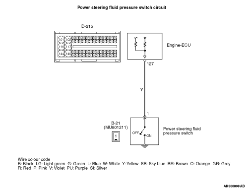
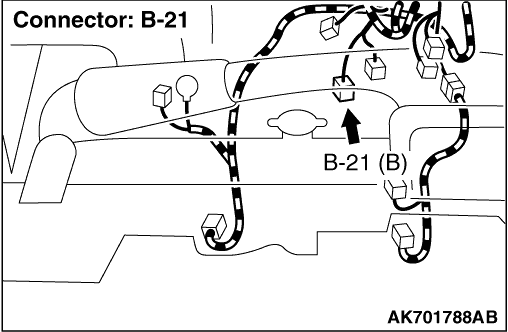
|
|
- Refer to Data List Reference Table
 . .
- Item 75: Power steering fluid pressure switch
|
|
|
Q.
Is the check result normal?
|
|
|
 Intermittent malfunction (Refer to GROUP 00 -
How to Use Troubleshooting/Inspection
Service Points -
How to Cope with Intermittent Malfunctions ). Intermittent malfunction (Refer to GROUP 00 -
How to Use Troubleshooting/Inspection
Service Points -
How to Cope with Intermittent Malfunctions ).
|
|
|
|
|
|
Q.
Is the check result normal?
|
|
|
 Repair or replace the connector. Repair or replace the connector.
|
|
|
|
|
|
- Disconnect B-21 power steering fluid pressure switch connector.
- Continuity between terminal No.1 and earth.
|
|
|
Q.
Is the check result normal?
|
|
|
Replace the power steering fluid pressure switch.
|
|
|
|
|
|
- Disconnect connector, and measure at harness side.
- Ignition switch: ON
- Voltage between terminal No.1 and earth.
|
|
|
Q.
Is the check result normal?
|
|
|
Q.
Is the check result normal?
|
|
|
Repair or replace the connector.
|
|
|
|
|
|
- Check output line for short circuit.
|
|
|
Q.
Is the check result normal?
|
|
|
Replace the engine-ECU. When the engine-ECU is replaced, write the chassis number
(Refer to GROUP 00 -
Precautions Before Service -
How to Perform Chassis Number
Writing ). After replacing the engine-ECU, register the injector identification
code and learn fuel injection (Refer to GROUP 00 -
Precautions Before Service -
What
The Common Rail Engine Learns ). After registering the injector
identification code, the vehicle equipped with the closed type DPF carries out the forcible
DPF regeneration. (Refer to GROUP 17 -
Diesel Particulate Filter (DPF) System -
Forcible
DPF Regeneration ).
|
|
|
|
|
|
Repair the damaged harness wire.
|
|
|
|
|
|
- Refer to Data List Reference Table .
- Item 75: Power steering fluid pressure switch
|
|
|
Q.
Is the check result normal?
|
|
|
Intermittent malfunction (Refer to GROUP 00 -
How to Use Troubleshooting/Inspection
Service Points -
How to Cope with Intermittent Malfunctions ).
|
|
|
|
|
|
Replace the engine-ECU. When the engine-ECU is replaced, write the chassis number
(Refer to GROUP 00 -
Precautions Before Service -
How to Perform Chassis Number
Writing ). After replacing the engine-ECU, register the injector identification
code and learn fuel injection (Refer to GROUP 00 -
Precautions Before Service -
What
The Common Rail Engine Learns ). After registering the injector
identification code, the vehicle equipped with the closed type DPF carries out the forcible
DPF regeneration. (Refer to GROUP 17 -
Diesel Particulate Filter (DPF) System -
Forcible
DPF Regeneration ).
|
|
|
|