Code No. P0428: No. 2 Exhaust Gas Temperature Sensor (catalyst temperature) Circuit High Input <Vehicles with closed type DPF>

OPERATION
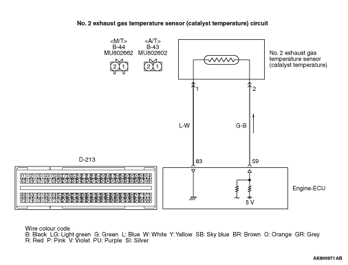
- A power voltage of 5 V is applied to the No. 2 exhaust gas temperature sensor
(catalyst temperature) output terminal (terminal No. 2) from the engine-ECU (terminal No. 59).
- The power voltage is earthed to the engine-ECU (terminal No. 83) from the No. 2
exhaust gas temperature sensor (catalyst temperature) (terminal No. 1).
FUNCTION
- The No. 2 exhaust gas temperature sensor (catalyst temperature) converts
the catalyst temperature into a voltage and inputs the voltage signal to the engine-ECU.
- Engine-ECU uses this voltage for DPF regeneration control.
- The No. 2 exhaust gas temperature sensor (catalyst temperature) is a kind of resistor,
which has characteristics to reduce its resistance as the catalyst temperature rises. Therefore,
the sensor output voltage varies with the catalyst temperature, and becomes lower as the catalyst temperature
rises.
TROUBLE JUDGMENT
Check Conditions
- Battery positive voltage is 8 -
16 V.
- 2 seconds later after the ignition switch has been in "ON" position or the engine
has started up.
- Vehicle speed is 20 km/h or higher.
- The No. 2 exhaust gas temperature sensor (catalyst temperature) output voltage is
4.95 V or more.
PROBABLE CAUSES
- Failed No. 2 exhaust gas temperature sensor (catalyst temperature)
- Open circuit or harness damage in No. 2 exhaust gas temperature sensor (catalyst
temperature) circuit or loose connector contact
- Failed engine-ECU
DIAGNOSTIC PROCEDURE |
STEP 1. M.U.T.-III data list |
|
|
Q.
Is the check result normal?
|
 Intermittent malfunction (Refer to GROUP 00 -
How to Use Troubleshooting/Inspection
Service Points -
How to Cope with Intermittent Malfunctions Intermittent malfunction (Refer to GROUP 00 -
How to Use Troubleshooting/Inspection
Service Points -
How to Cope with Intermittent Malfunctions  ). ). |
|
 Go to Step 2 . Go to Step 2 . |
|
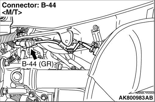
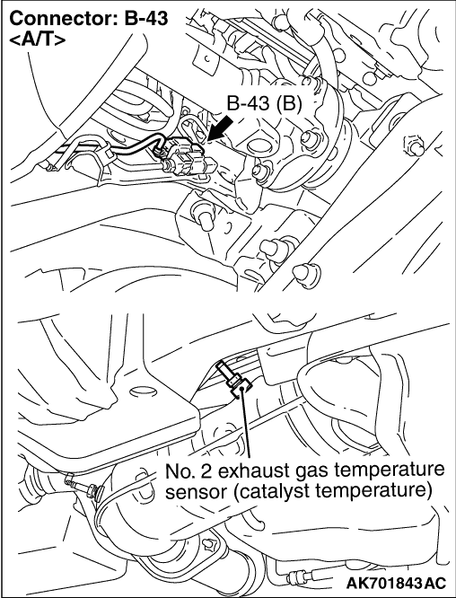
STEP 2. Connector check: B-44 <M/T>, B-43 <A/T> No. 2 exhaust gas temperature sensor (catalyst temperature) connector |
Q.
Is the check result normal?
|
| Go to Step 3 . |
|
| Repair or replace the connector. |
|
STEP 3. Check No. 2 exhaust gas temperature sensor (catalyst temperature) itself. |
|
Q.
Is the check result normal?
|
| Go to Step 4 . |
|
| Replace the No. 2 exhaust gas temperature sensor (catalyst temperature). After
replacing the No. 2 exhaust gas temperature sensor (catalyst temperature), carry out the forcible
DPF regeneration. (Refer to GROUP 17 -
Diesel Particulate Filter (DPF) System -
Forcible
DPF Regeneration ). |
|
STEP 4. Perform voltage measurement at B-44 <M/T>, B-43 <A/T> No. 2 exhaust gas temperature sensor (catalyst temperature) connector. |
|
| OK: 4.5 -
4.9 V |
Q.
Is the check result normal?
|
| Go to Step 8 . |
|
| Go to Step 5 . |
|
STEP 5. Connector check: D-213 engine-ECU connector. |
Q.
Is the check result normal?
|
| Go to Step 6 . |
|
| Repair or replace the connector. |
|
STEP 6. Check harness between B-44 <M/T>, B-43 <A/T> (terminal No. 2) No. 2 exhaust gas temperature sensor (catalyst temperature) connector and D-213 (terminal No. 59) engine-ECU connector. |
|
Q.
Is the check result normal?
|
| Go to Step 7 . |
|
| Repair the damaged harness wire. |
|
STEP 7. M.U.T.-III data list |
|
|
Q.
Is the check result normal?
|
| Intermittent malfunction (Refer to GROUP 00 -
How to Use Troubleshooting/Inspection
Service Points -
How to Cope with Intermittent Malfunctions ). |
|
| Replace the engine-ECU. When the engine-ECU is replaced, write the chassis number
(Refer to GROUP 00 -
Precautions Before Service -
How to Perform Chassis Number
Writing ). After replacing the engine-ECU, register the injector identification
code and learn fuel injection (Refer to GROUP 00 -
Precautions Before Service -
What
The Common Rail Engine Learns ). After registering the injector
identification code, carry out the forcible DPF regeneration. (Refer to GROUP 17 -
Diesel
Particulate Filter (DPF) System -
Forcible DPF Regeneration ). |
|
STEP 8. Perform resistance measurement at B-44 <M/T>, B-43 <A/T> No. 2 exhaust gas temperature sensor (catalyst temperature) connector. |
|
| OK: Continuity (2 Ω
or less) |
Q.
Is the check result normal?
|
| Go to Step 11 . |
|
| Go to Step 9 . |
|
STEP 9. Connector check: D-213 engine-ECU connector |
Q.
Is the check result normal?
|
| Go to Step 10 . |
|
| Repair or replace the connector. |
|
STEP 10. Check harness between B-44 <M/T>, B-43 <A/T> (terminal No. 1) No. 2 exhaust gas temperature sensor (catalyst temperature) connector and D-213 (terminal No. 83) engine-ECU connector. |
|
Q.
Is the check result normal?
|
| Go to Step 7 . |
|
| Repair the damaged harness wire. |
|
STEP 11. Connector check: D-213 engine-ECU connector. |
Q.
Is the check result normal?
|
| Go to Step 12 . |
|
| Repair or replace the connector. |
|
STEP 12. Check harness between B-44 <M/T>, B-43 <A/T> (terminal No. 2) No. 2 exhaust gas temperature sensor (catalyst temperature) connector and D-213 (terminal No. 59) engine-ECU connector. |
|
Q.
Is the check result normal?
|
| Go to Step 7 . |
|
| Repair the damaged harness wire. |
|