Code No. P0003: Suction Control Valve Open <Euro5b>


OPERATION
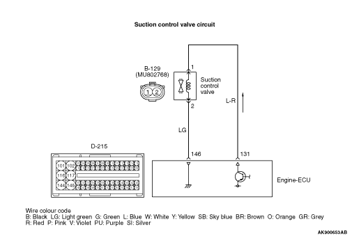
- The current is applied from the engine-ECU (terminal No. 131) to the suction control valve (terminal No. 1) and earthed to the engine-ECU (terminal No. 146) from the suction control valve (terminal No. 2).
FUNCTION
- The engine-ECU performs duty control over the suction control valve.
- The engine-ECU checks whether the amount of current for driving duty is adequate.
TROUBLE JUDGMENT
Check Conditions
- Battery positive voltage is 8 - 16 V
- 2 seconds later after the ignition switch has been in "ON" position or the engine has started up.
- The supply pump and injector are being normally controlled.
- The fuel injection amount is 4 mm3/st or more.
- When the driving duty ratio of the suction control valve is higher than the specified value, the driving current is lower than the specified value.
PROBABLE CAUSES
- Failed suction control valve
- Open circuit or harness damage in suction control valve circuit or loose connector contact
- Failed engine-ECU
DIAGNOSIS PROCEDURE |
STEP 1. Connector check: B-129 suction control valve connector |
Q.
Is the check result normal?
|
 Go to Step 2. Go to Step 2. |
|
 Repair or replace the connector. Repair or replace the connector. |
|
STEP 2. Check suction control valve itself. |
|
Q.
Is the check result normal?
|
| Go to Step 3. |
|
Replace the suction control valve. After replacing the suction control valve, learn the supply pump (Refer to GROUP 00 - Precautions Before Service - What The Common Rail Engine Learns  ). ). |
|
STEP 3. Connector check: D-215 engine-ECU connector. |
Q.
Is the check result normal?
|
| Go to Step 4. |
|
| Repair or replace the connector. |
|
STEP 4. Check harness between D-215 (terminal No. 131) engine-ECU connector and B-129 (terminal No. 1) suction control valve connector. |
|
Q.
Is the check result normal?
|
| Go to Step 5. |
|
| Repair the damaged harness wire. |
|
STEP 5. Check harness between D-215 (terminal No. 146) engine-ECU connector and B-129 (terminal No. 2) suction control valve connector. |
|
Q.
Is the check result normal?
|
| Go to Step 6. |
|
| Repair the damaged harness wire. |
|
STEP 6. M.U.T.-III diagnosis code |
|
Q.
Is the diagnosis code set?
|
| Replace the engine-ECU. When the engine-ECU is replaced, write the chassis number (Refer to GROUP 00 - Precautions Before Service - How to Perform Chassis Number Writing ). After replacing the engine-ECU, register the injector identification code and learn fuel injection (Refer to GROUP 00 - Precautions Before Service - What The Common Rail Engine Learns ). After registering the injector identification code, the vehicle equipped with the closed type DPF carries out the forcible DPF regeneration. (Refer to GROUP 17 - Diesel Particulate Filter (DPF) System - Forcible DPF Regeneration ). |
|
| Intermittent malfunction (Refer to GROUP 00 - How to Use Troubleshooting/Inspection Service Points - How to Cope with Intermittent Malfunctions ). |
|