|
|
- Measure battery voltage during cranking.
|
|
|
Q.
Is the check result normal?
|
|
|
 Check battery (Refer to GROUP 54A -
Battery -
On-vehicle Service -
Battery
Test Check battery (Refer to GROUP 54A -
Battery -
On-vehicle Service -
Battery
Test  ). ).
|
|
|
|
|
|
OK:
ON (Ignition switch: ST)
OFF (Ignition switch: ON)
|
|
|
Q.
Is the check result normal?
|
|
|
Q.
Is the check result normal?
|
|
|
- Check starter relay itself (Refer to GROUP 16 -
Starting System -
On-vehicle
Service -
Starter Relay Check <4M4> ).
|
|
|
Q.
Is the check result normal?
|
|
|
Replace the starter relay.
|
|
|
|
|
|
- Remove starter relay
- Resistance between terminal No.1 and earth
|
|
|
OK: Continuity (2 Ω
or less)
|
|
|
Q.
Is the check result normal?
|
|
|
Check and repair the harness wire.
|
|
|
|
|
|
- Disconnect connector, measure the harness side.
- Voltage between terminal No. 3 and earth.
- Ignition switch: ST
|
|
|
Q.
Is the check result normal?
|
|
|
Q.
Is the check result normal?
|
|
|
- Check ignition switch itself (Refer to GROUP 54A -
Ignition switch -
Inspection -
Ignition
switch inspection
|
|
|
Q.
Is the check result normal?
|
|
|
Replace the ignition switch.
|
|
|
|
|
|
Q.
Is the check result normal?
|
|
|
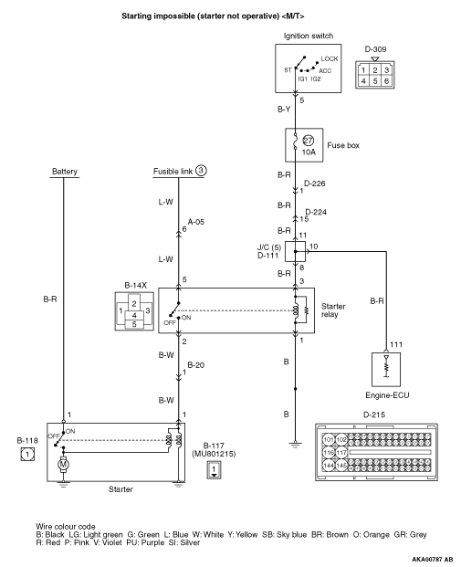
 Check intermediate connectors C-111, D-224 and D-226, and repair if necessary.
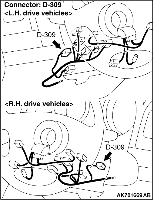
If intermediate connectors are normal, check and repair harness between D-309 (terminal No.
5) ignition switch connector and B-14X (terminal No. 3) starter relay connector. Check intermediate connectors C-111, D-224 and D-226, and repair if necessary.
If intermediate connectors are normal, check and repair harness between D-309 (terminal No.
5) ignition switch connector and B-14X (terminal No. 3) starter relay connector.
|
|
|
|
|
|
- Disconnect connector, measure the harness side.
- Voltage between terminal No. 5 and earth.
|
|
|
Q.
Is the check result normal?
|
|
|
Check intermediate connector A-05, and repair if necessary. If intermediate connector
is normal, check and repair harness between battery and B-14X (terminal No. 5) starter relay
connector.
|
|
|
|
|
|
Q.
Are the check results normal?
|
|
|
- Disconnect connector, measure the harness side.
- Voltage between terminal No. 1 and earth.
|
|
|
Q.
Is the check result normal?
|
|
|
Check and repair the harness wire.
|
|
|
|
|
|
- Disconnect connector, measure the harness side.
- Voltage between terminal No. 1 and earth.
- Ignition switch: ST
|
|
|
Q.
Is the check result normal?
|
|
|
Check intermediate connector B-20, and repair if necessary. If intermediate connector
is normal, check and repair harness between B-14X (terminal No. 2) starter relay connector and
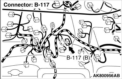
B-117 (terminal No. 1) starter connector.
|
|
|
|
|
|
Q.
Is the check result normal?
|
|
|
- Check ignition switch itself (Refer to GROUP 54A -
Ignition switch -
Inspection -
Ignition
switch inspection ).
|
|
|
Q.
Is the check result normal?
|
|
|
Replace the ignition switch.
|
|
|
|
|
|
Q.
Is the check result normal?
|
|
|
Check intermediate connectors C-111, D-224 and D-226, and repair if necessary.
If intermediate connectors are normal, check and repair harness between D-309 (terminal No.
5) ignition switch connector and D-215 (terminal No. 111) engine-ECU connector.
|
|
|
|