REMOVAL AND INSTALLATION


Post-installation Operation
  • Fuel Line Air Breeding (Refer to GROUP 13B - On-vehicle Service, Evacuation of Air from Fuel Line ).
  • Checking for Fuel Leaks


<RH drive vehicles and LH drive vehicles (vehicles without fuel line heater)>


Removal steps


1.
Water level sensor connector connection


2.
Fuel filter pressure switch connector connection <LH drive vehicles (emission regulation step III)>

>>B<<
3.
Fuel feed hose connection

>>B<<
4.
Fuel return hose connection


5.
Fuel filter assembly


6.
Drain plug and O-ring


7.
Water level sensor
<<A>>
>>A<<
8.
Fuel filter cartridge


9.
Fuel filter pump


10.
Fuel filter bracket

<LH drive vehicles (vehicles with fuel line heater)>


Removal steps


1.
Water level sensor connector connection


2.
Fuel filter pressure switch connector connection <emission regulation step III>

>>B<<
3.
Fuel feed hose connection

>>B<<
4.
Fuel return hose

>>B<<
5.
Fuel return line hose

>>B<<
6.
Fuel return line hose


7.
Fuel filter assembly


8.
Drain plug and O-ring


9.
Water level sensor
<<A>>
>>A<<
10.
Fuel filter cartridge


11.
Fuel filter pump


12.
Fuel filter bracket

REMOVAL SERVICE POINT


<<A>> FUEL FILTER CARTRIDGE REMOVAL


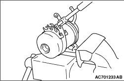
Fix the fuel filter pump to a vice, and then remove the fuel filter cartridge using an oil filter wrench.

INSTALLATION SERVICE POINTS


>>A<< FUEL FILTER CARTRIDGE INSTALLATION


1.Clean the mounting surface on the fuel filter pump side.
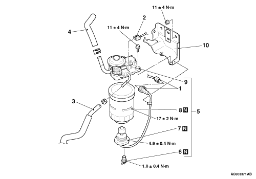
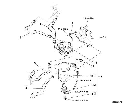
2.Tighten the fuel filter cartridge to the specified torque from the point where the gasket contacts the mounting surface.
Tightening torque: Approximately 3/4 - 1 turn (17 ± 2 N·m)

>>B<< FUEL RETURN LINE HOSE/FUEL RETURN HOSE/FUEL FEED HOSE INSTALLATION


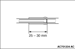
If the pipe has a stepped part, connect securely up to the stepped part. If the pipe has no stepped part, insert so that the inserted portion 25 - 30 mm long.