ADJUSTMENT OF TRANSMISSION
SPACER SELECTION FOR ADJUSTMENT OF MAINDRIVE GEAR BEARING AXIAL PLAY
<Measurement using a solder> |
|
|
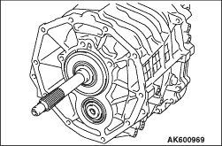 |
1.Install the main drive pinion to the transmission case. |
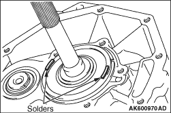 |
2.Put solders (1.0 mm diameter, about 10 mm long) on the ball bearing at the positions shown
in the illustration. 3.Install the clutch housing and tighten the bolts to the specified torque of 35 ± 6 N·m. 4.Remove the clutch housing and remove the solder. 5.If the solders have not crushed, use thicker solders (1.6 mm diameter, about 10 mm long) and repeat steps 2 to 4. |
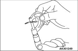 |
6.Measure the thickness of the crushed solder with a micrometer and select spacers that
will provide the standard value. Spacer thickness: (T1 - 0) to (T1 - 0.1) T1: The crushed solder thickness mm Standard value: 0 - 0.1 mm |
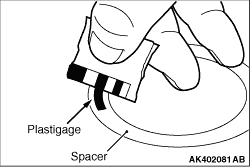
<Measurement using plastigage> |
|
1.Install the main drive pinion to the transmission case. 2.Installs the adjusting spacer having the minimum thickness. |
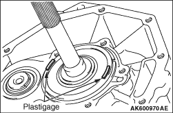 |
3.Put plastigage (about 10 mm long) on the ball bearing at the positions shown in the illustration. 4.Install the clutch housing and tighten the bolts to the specified torque of 35 ± 6 N·m. 5.Remove the clutch housing and take out the crushed plastigage. |
 |
6.If the plastigages have not crushed, replace the spacer with a thicker one and repeat
steps 3 to 5. 7.Measure the width of the crushed Plastigage at its widest part using a scale printed on the plastigage package. Spacer thickness: (T2 + T3 - 0) to (T2 + T3 - 0.1) Spacer thickness: (T2 + T3 - 0) to (T2 + T3 - 0.1) T3: The spacer thickness used for measurement mm Standard value: 0 - 0.1 mm |