Inspection Procedure 16: 4LLc detection switch system
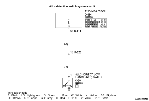

OPERATION
- System voltage is applied to the 4LLc detection switch output terminal (terminal
No.1) from the ECU via the resistance in the unit.
- The 4LLc detection switch is grounded through the transfer case to the vehicle body.
COMMENTS ON TROUBLE SYMPTOM
PROBABLE CAUSES
- Malfunction of the 4LLc detection switch
- Damaged harness wires and connectors
- Malfunction of the engine-A/T-ECU
DIAGNOSIS PROCEDURE |
STEP 1. M.U.T.-III data list |
Item 31: 4LLc detection switch (Refer to data list reference table  ). ). |
Q.
Is the check result normal?
|
 Intermittent malfunction (Refer to GROUP 00 - How to Cope with Intermittent
Malfunction ). Intermittent malfunction (Refer to GROUP 00 - How to Cope with Intermittent
Malfunction ). |
|
 Go to Step 2. Go to Step 2. |
|
STEP 2. Check the 4LLc detection switch. |
| Refer to . |
Q.
Is the check result normal?
|
| Go to Step 3. |
|
| Replace the 4LLc detection switch. |
|
STEP 3. Measure the voltage at 4LLc detection switch connector C-09. |
| (1)Disconnect the connector, and measure the voltage between terminal No.1 and earth
at the wiring harness side. |
| (2)Turn the ignition switch to the ON position. OK: System voltage |
Q.
Is the check result normal?
|
| Go to Step 4. |
|
| Go to Step 5. |
|
STEP 4. M.U.T.-III data list |
| Item 31: 4LLc detection switch (Refer to data list reference table ). |
Q.
Is the check result normal?
|
| Intermittent malfunction (Refer to GROUP 00 - How to Cope with Intermittent
Malfunction ). |
|
| Replace the engine-A/T-ECU. |
|
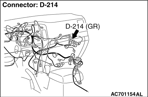
STEP 5. Measure the voltage at engine-A/T-ECU connector D-214. |
| (1)Disconnect 4LLc detection switch connector C-09. |
| (2)Turn the ignition switch to the ON position. |
| (3)Measure the voltage between engine-A/T-ECU connector D-214 terminal No.55 and earth. OK: System voltage |
Q.
Is the check result normal?
|
| Go to Step 6. |
|
| Go to Step 8. |
|
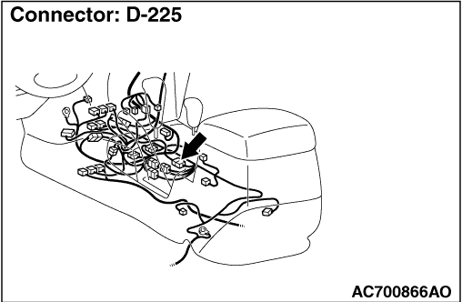
STEP 6. Connector check: C-09 4LLc detection switch connector, D-225 intermediate connector, D-214 engine-A/T-ECU connector |
| Check for the contact with terminals. |
Q.
Is the check result normal?
|
| Go to Step 7. |
|
| Repair the defective connector. |
|
STEP 7. Check the harness between 4LLc detection switch connector C-09 terminal No.1 and engine-A/T-ECU connector D-214 terminal No.55. |
| Check the power supply line for open circuit. |
Q.
Is the check result normal?
|
| Go to Step 4. |
|
| Repair the wiring harness. |
|
STEP 8. Connector check: C-09 4LLc detection switch connector, D-225 intermediate connector, D-214 engine-A/T-ECU connector |
| Check for the contact with terminals. |
Q.
Is the check result normal?
|
| Go to Step 9. |
|
| Repair the defective connector. |
|
STEP 9. Check the harness between 4LLc detection switch connector C-09 terminal No.1 and engine-A/T-ECU connector D-214 terminal No.55. |
| Check the power supply line for short circuit. |
Q.
Is the check result normal?
|
| Go to Step 4. |
|
| Repair the wiring harness. |
|