|
|
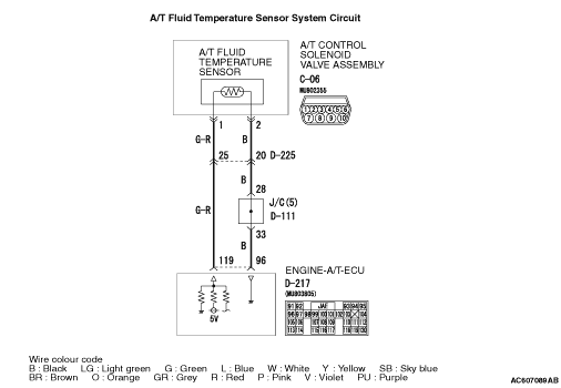
Item 7: A/T fluid temperature sensor (Refer to Data List Table  ). ).
|
|
|
Q.
Is the check result normal?
|
|
|
 Intermittent malfunction (Refer to GROUP 00 - How to Cope with Intermittent Malfunction ). Intermittent malfunction (Refer to GROUP 00 - How to Cope with Intermittent Malfunction ).
|
|
|
|
|
|
Disconnect the connector, and measure the resistance between terminal 1 and 2 at the sensor side.
|
|
|
OK:
- 16.7 - 20.5 kΩ (at 0°C)
- 7.3 - 8.9 kΩ (at 20°C)
- 3.4 - 4.2 kΩ (at 40°C)
- 1.9 - 2.2 kΩ (at 60°C)
- 1.0 - 1.2 kΩ (at 80°C)
- 0.57 - 0.69 kΩ (at 100°C)
|
|
|
Q.
Is the check result normal?
|
|
|
 Replace the A/T fluid temperature sensor. Replace the A/T fluid temperature sensor.
|
|
|
|
|
|
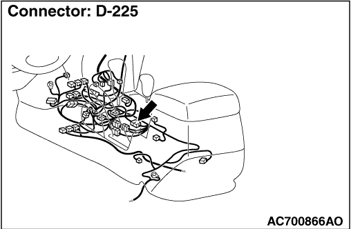
Check for the contact with terminals.
|
|
|
Q.
Is the check result normal?
|
|
|
Repair the defective connector.
|
|
|
|
|
|
Disconnect the connector, and measure the resistance between terminal 2 and earth at the wiring harness side.
|
|
|
OK: Continuity (Less than 2 Ω)
|
|
|
Q.
Is the check result normal?
|
|
|
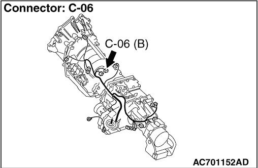
(1)Connect A/T control solenoid valve assembly connector C-06.
|
|
|
(2)Turn the ignition switch to the ON position.
|
|
|
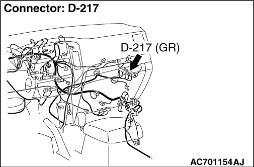
(3)Measure the voltage between engine-A/T-ECU connector D-217 terminal No.96 and earth.
OK: 0.5 V or less
|
|
|
Q.
Is the check result normal?
|
|
|
Check for the contact with terminals.
|
|
|
Q.
Is the check result normal?
|
|
|
Repair the defective connector.
|
|
|
|
|
|
Item 7: A/T fluid temperature sensor (Refer to Data List Table ).
|
|
|
Q.
Is the check result normal?
|
|
|
Intermittent malfunction (Refer to GROUP 00 - How to Cope with Intermittent Malfunction ).
|
|
|
|
|
|
Replace the engine-A/T-ECU.
|
|
|
|
|
|
(1)Disconnect the connector, and measure the voltage between terminal 1 and earth at the wiring harness side.
|
|
|
(2)Turn the ignition switch to the ON position.
OK: 4.5 - 4.9 V
|
|
|
Q.
Is the check result normal?
|
|
|
(1)Connect A/T control solenoid valve assembly connector C-06.
|
|
|
(2)Turn the ignition switch to the ON position.
|
|
|
(3)Measure the voltage between engine-A/T-ECU connector D-217 terminal No.119 and earth.
OK:
- 3.8 - 4.0 V (at 20°C)
- 3.2 - 3.4 V (at 40°C)
- 1.7 - 1.9 V (at 80°C)
|
|
|
Q.
Is the check result normal?
|
|
|
Check for the contact with terminals.
|
|
|
Q.
Is the check result normal?
|
|
|
Repair the defective connector.
|
|
|
|
|
|
Check for the contact with terminals.
|
|
|
Q.
Is the check result normal?
|
|
|
Repair the defective connector.
|
|
|
|
|
|
Check the output line for short circuited and open circuit.
|
|
|
Q.
Is the check result normal?
|
|
|
Repair the wiring harness.
|
|
|
|
|
|
Check for the contact with terminals.
|
|
|
Q.
Is the check result normal?
|
|
|
Repair the defective connector.
|
|
|
|
|
|
Check the earth line for open circuit.
|
|
|
Q.
Is the check result normal?
|
|
|
Repair the wiring harness.
|
|
|
|