|
|
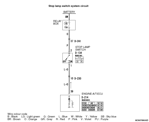
The stop lamps should illuminate when the brake pedal is depressed, and extinguish when
released.
|
|
|
Q.
Is the check result normal?
|
|
|
Refer to GROUP 35A - On-vehicle Service, Brake Pedal Check and Adjustment  . .
|
|
|
Q.
Is the check result normal?
|
|
|
 Adjust the brake pedal height. Adjust the brake pedal height.
|
|
|
|
|
|
Refer to GROUP 35A - Brake Pedal .
|
|
|
Q.
Is the check result normal?
|
|
|
Replace the stop lamp switch.
|
|
|
|
|
|
Item 19: Stop lamp switch (Refer to data list reference table ).
|
|
|
Q.
Is the check result normal?
|
|
|
 Intermittent malfunction (Refer to GROUP 00 - How to Cope with Intermittent
Malfunction ). Intermittent malfunction (Refer to GROUP 00 - How to Cope with Intermittent
Malfunction ).
|
|
|
|
|
|
Check for the contact with terminals.
|
|
|
Q.
Is the check result normal?
|
|
|
Repair the defective connector.
|
|
|
|
|
|
Disconnect the connector, and measure the voltage between terminal No.2 and earth at the
harness side.
|
|
|
Q.
Is the check result normal?
|
|
|
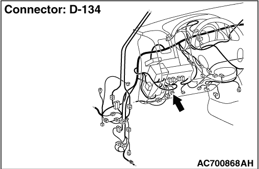
(1)Connect stop lamp switch connector D-134.
|
|
|
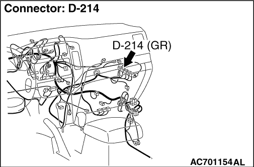
(2)Measure the voltage between engine-A/T-ECU connector D-214 terminal No.39
and earth.
OK:
Brake pedal depressed: System voltage
Brake pedal not depressed: 1 V or less
|
|
|
Q.
Is the check result normal?
|
|
|
Check for the contact with terminals.
|
|
|
Q.
Is the check result normal?
|
|
|
Repair the defective connector.
|
|
|
|
|
|
Item 19: Stop lamp switch (Refer to data list reference table ).
|
|
|
Q.
Is the check result normal?
|
|
|
Intermittent malfunction (Refer to GROUP 00 - How to Cope with Intermittent
Malfunction ).
|
|
|
|
|
|
Replace the engine-A/T-ECU.
|
|
|
|
|
|
Check for the contact with terminals.
|
|
|
Q.
Is the check result normal?
|
|
|
Repair the defective connector.
|
|
|
|
|
|
Check the output line for short and open circuit.
|
|
|
Q.
Is the check result normal?
|
|
|
Repair the wiring harness.
|
|
|
|
|
|
Check for the contact with terminals.
|
|
|
Q.
Is the check result normal?
|
|
|
Repair the defective connector.
|
|
|
|
|
|
Check the power supply line for short and open circuit.
|
|
|
Q.
Is the check result normal?
|
|
|
Repair the wiring harness.
|
|
|
|