REMOVAL AND INSTALLATION


<Vehicles with 3200 except A/T-short wheelbase for Europe step 4>


Removal steps


1.
Rear differential lock switch


2.
Transfer control unit

>>A<<
3.
Cable band

>>A<<
4.
Air hose (A)

>>A<<
5.
Cable band

>>A<<
6.
Air hose (B)

>>A<<
7.
Differential lock switch harness


8.
Air pipe bracket assembly


9.
Air breather hose


10.
Nipple


11.
Air pump assembly


12.
Rear differential lock detection switch (Refer to .)


13.
Gasket

<Vehicles with 3000, 3800 and 3200-A/T-Short wheelbase for Europe step 4>


Removal steps


1.
Rear differential lock switch


2.
Transfer control unit


3.
Hose


4.
Vapour hose


5.
Nipple


6.
Rear differential lock air pump assembly


7.
Rear differential lock detection switch (Refer to .)


8.
Gasket

INSTALLATION SERVICE POINT


>>A<< DIFFERENTIAL LOCK SWITCH HARNESS/AIR HOSE (B)/CABLE BAN/AIR HOSE (A) INSTALLATION


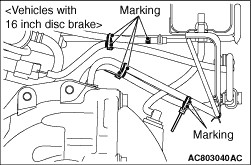
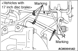
Locate the markings as shown in the figure and tie the centre of markings with cable band.