REMOVAL AND INSTALLATION


caution
  • As for vehicles with headlamp auto levelling system, disconnect the height sensor from the lower arm before operation to prevent damages to the height sensor (Refer to GROUP 54A - Height Sensor ). <Vehicles with headlamp automatic levelling system>
  • *: Indicates parts which should be temporarily tightened, and then fully tightened with the vehicle on the earth in an unladen condition.
  • When the suspension is adjusted or replaced, the calibration of steering wheel sensor must be performed (Refer to GROUP 35C- On-vehicle Service- Steering Wheel Sensor Initialisation ).
Post-installation Operation
  • Check the Dust Cover for Cracks or Damage by Pushing it with Your Finger.
  • Wheel Alignment Check and Adjustment (Refer to ).


Removal steps


1.
Front height sensor and upper arm connection nut <Vehicles with headlamp automatic levelling system>


2.
Front wheel speed sensor clamp mounting bolt


3.
Clip


4.
Brake hose


5.
Split pin
<<A>>

6.
Upper arm ball joint and knuckle connection nut


7.
Upper arm mounting bolt


8.
Upper arm assembly


9.
Upper arm and upper arm ball joint connection bolt
<<A>>

10.
Upper arm ball joint assembly

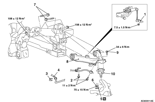
REMOVAL SERVICE POINT


<<A>> UPPER ARM BALL JOINT ASSEMBLY REMOVAL


caution
  • Do not remove the nut from ball joint. Loosen it and use the special tool to avoid possible damage to ball joint threads.

  • Hang the special tool with a cord to prevent it from falling.

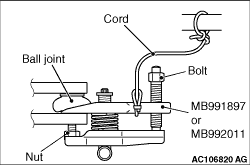
1.Install special tool ball joint remover (MB991897 or MB992011) as shown in the figure.

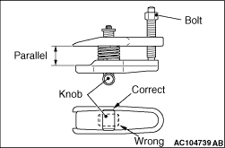
2.Turn the bolt and knob as necessary to make the jaws of special tool parallel, tighten the bolt by hand and confirm that the jaws are still parallel.
note When adjusting the jaws in parallel, make sure the knob is in the position shown in the figure.
3.Tighten the bolt with a wrench to disconnect the ball joint.