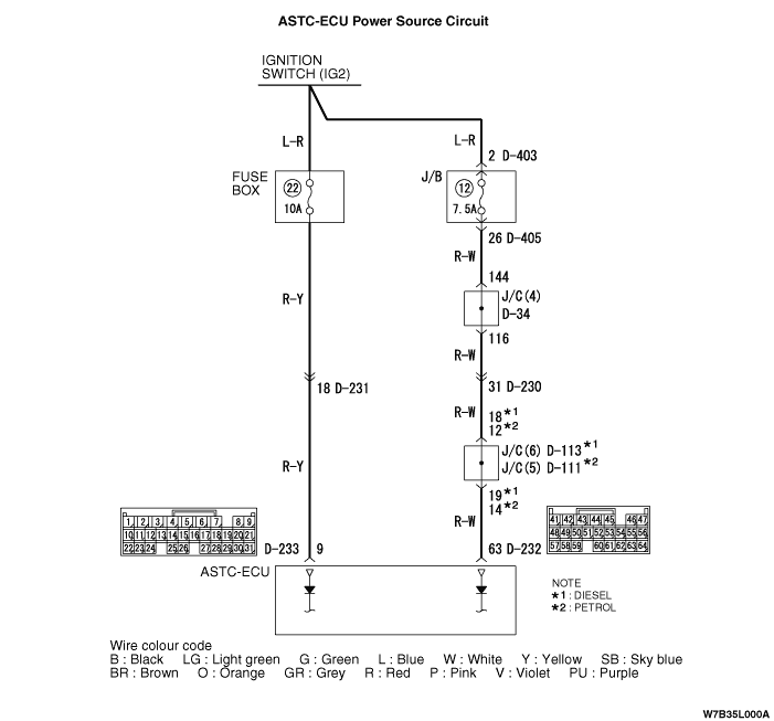
Code No.16: ASTC-ECU power supply system (extreme voltage drop or rise)
| caution | If the battery voltage drops or rises while making this check, Diagnosis code No.16 is set as an existing problem, making it impossible to perform correct trouble diagnosis. Before carrying out the following diagnosis, test the battery and charge it if necessary. |
OPERATION
DIAGNOSIS CODE SET CONDITIONS
PROBABLE CAUSES
- Damaged wiring harness or connector
- Malfunction of the battery
- Malfunction of the charging system
- Malfunction of the ASTC-ECU
DIAGNOSIS |
STEP 1. Check the battery. |
Refer to GROUP 54A, Battery - On-vehicle Service - Battery Test  . . |
Q.
Is the battery damaged?
|
 Charge or replace the battery. Then go to Step 4. Charge or replace the battery. Then go to Step 4. |
|
 Go to Step 2. Go to Step 2. |
|
STEP 2. Check the charging system. |
| Refer to GROUP 16, Charging System - On-vehicle Service - Wave Pattern Check Using an Oscilloscope . |
Q.
Is the charging system damaged?
|
| Repair the Charging System. Then go to Step 4. |
|
| Go to Step 3. |
|
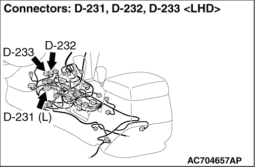
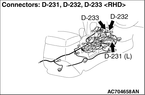
STEP 3. Check ASTC-ECU connector D-233 for loose, corroded or damaged terminals, or terminals pushed back in the connector. |
Q.
Is the check result normal?
|
| Go to Step 4. |
|
| Repair or replace it. Then go to Step 12. |
|
STEP 4. Check the power supply circuit at ASTC-ECU harness connector D-233. |
| (1)Disconnect ASTC-ECU connector D-233 and measure at the harness connector (harness side). |
| (2)Start the engine. |
| (3)Measure the voltage between terminal 9 and body earth. OK: Approx. 12 volts (battery positive voltage) |
Q.
Is battery positive voltage (approx. 12 volts) present?
|
| Go to Step 7. |
|
| Go to Step 5. |
|
STEP 5. Check intermediate connector D-231 for loose, corroded or damaged terminals, or terminals pushed back in the connector. |
Q.
Is the check result normal?
|
| Go to Step 6. |
|
| Repair or replace it. Then go to Step 12. |
|
STEP 6. Check the harness wires between ASTC-ECU connector D-233 (terminal 9) and multi-purpose fuse number 22 (fuse box). |
Q.
Is the check result normal?
|
| Go to Step 11. |
|
| Repair or replace it. Then go to Step 12. |
|
STEP 7. Check ASTC-ECU connector D-232 for loose, corroded or damaged terminals, or terminals pushed back in the connector. |
Q.
Is the check result normal?
|
| Go to Step 8 |
|
| Repair or replace it. Then go to Step 12. |
|
STEP 8. Check the power supply circuit at ASTC-ECU harness connector D-232. |
| (1)Disconnect ASTC-ECU connector D-232 and measure at the harness connector (harness side). |
| (2)Start the engine. |
| (3)Measure the voltage between terminal 63 and body earth. OK: Approx. 12 volts (battery positive voltage) |
Q.
Is battery positive voltage (approx. 12 volts) present?
|
| Go to Step 11. |
|
| Go to Step 9. |
|
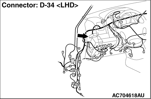
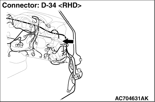
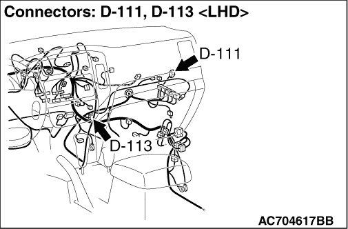
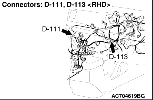
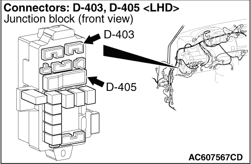
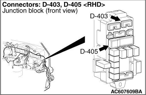
STEP 9. Check intermediate connectors D-113 <4M4>, D-111 <6G7>, D-34, junction block connector D-403 and junction block connector D-405 for loose, corroded or damaged terminals, or terminals pushed back in the connector. |
Q.
Is the check result normal?
|
| Go to Step 10. |
|
| Repair or replace it. Then go to Step 12. |
|
STEP 10. Check the harness wires between ASTC-ECU connector D-232 (terminal 63) and junction block connector D-403 (terminal 2). |
Q.
Is the check result normal?
|
| Go to Step 11. |
|
| Repair or replace it. Then go to Step 12. |
|
STEP 11. Recheck for diagnosis code. |
| (1)Erase the diagnosis code memory. |
| (2)Recheck for diagnosis code. |
Q.
Is code No.16 set?
|
| Replace the ASTC-ECU (Refer to GROUP 35C, ASTC-ECU ). Then go to Step 12. |
|
| It can be assumed that this malfunction is intermittent. Refer to GROUP 00, How to Use Troubleshooting/Inspection Service Points - How to Cope with Intermittent Malfunction . |
|
STEP 12. Recheck for diagnosis code. |
| (1)Erase the diagnosis code memory. |
| (2)Recheck for diagnosis code. |
Q.
Is code No.16 set?
|
| Start over at Step 1. |
|
| The procedure is complete. |
|