|
|
When the ignition switch is turned to the LOCK (OFF) position, check if the pump motor
operates.
|
|
|
Q.
Does the pump motor continue rotating?
|
|
|
Remove the motor relay 1.
|
|
|
Q.
Does the pump motor stop?
|
|
|
 Replace the motor relay 1. Then go to Step 17. Replace the motor relay 1. Then go to Step 17.
|
|
|
|
|
|
Remove the motor relay 2.
|
|
|
Q.
Does the pump motor stop?
|
|
|
Replace the motor relay 2. Then go to Step 17.
|
|
|
|
|
|
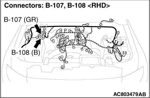
(1)Disconnect HBB connector B-108.
|
|
|
(2)Measure the voltage between terminal 31 and body earth.
OK: 0 volt
|
|
|
Q.
Is the measured voltage 0 volt?
|
|
|
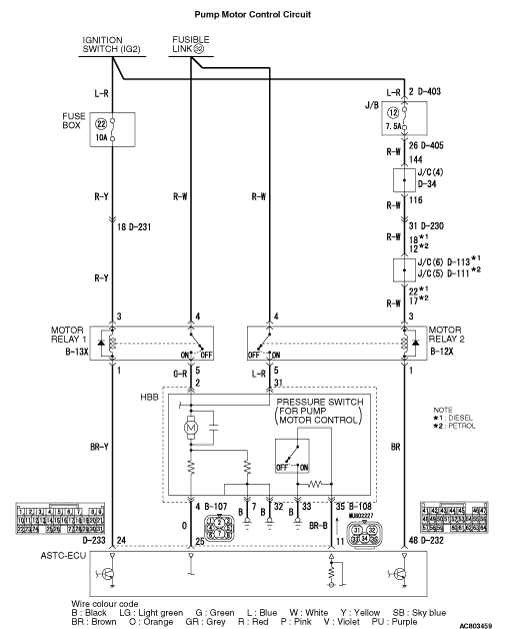
The wire between motor relay 2 connector B-12X (terminal 5) and HBB connector B-108 (terminal
31)
|
|
|
Q.
Is the harness wire damaged?
|
|
|
Repair or replace it. Then go to Step 16.
|
|
|
|
|
|
(1)Disconnect HBB connector B-107.
|
|
|
(2)Measure the voltage between terminal 2 and body earth.
OK: 0 volt
|
|
|
Q.
Is the measured voltage 0 volt?
|
|
|
Q.
Is the check result normal?
|
|
|
 Repair or replace it. Then go to Step 17. Repair or replace it. Then go to Step 17.
|
|
|
|
|
|
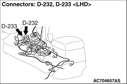
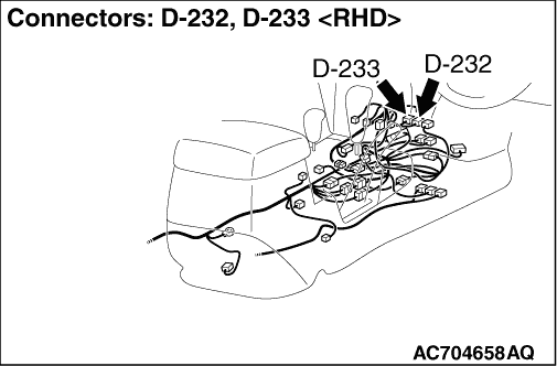
- The wire between motor relay 2 connector B-12X (terminal 1)
and ASTC-ECU connector D-232 (terminal 48)
- The wire between motor relay 1 connector B-13X (terminal 1) and ASTC-ECU connector
D-233 (terminal 24)
|
|
|
Q.
Is the check result normal?
|
|
|
Repair or replace it. Then go to Step 17.
|
|
|
|
|
|
(1)Disconnect ASTC-ECU connector D-233 and measure at the harness connector (component
side).
|
|
|
(2)Measure the resistance between terminal 11 and body earth.
OK: Continuity exists (2 Ω
or less)
|
|
|
Q.
Is the measured resistance 2 Ω
or less?
|
|
|
Q.
Is the check result normal?
|
|
|
Repair or replace it. Then go to Step 17.
|
|
|
|
|
|
(1)Depress the pedal repeatedly more than 40 times until the pedal depressing force
feels heavy with the ignition switch at the "LOCK" (OFF) position to release the pressure of HBB
power supply system.
|
|
|
(2)Disconnect HBB connector B-108.
|
|
|
(3)Measure the resistance between the terminals 33 and 35 at the HBB.
OK: Approx. 1 kΩ
|
|
|
(4)Connect HBB connector B-108 to the vehicle wiring harness, and then turn the ignition
switch ON. The pump motor should run and then stop. Turn the ignition switch to the LOCK (OFF)
position to disconnect HBB connector B-108. At the HBB side, measure the resistance value (at
high accumulator pressure) between Nos. 33 and 35 terminals.
OK: Continuity exists (2 Ω
or less)
|
|
|
Q.
Is the check result normal?
|
|
|
Replace the master cylinder and hydraulic unit assembly (Refer to  ).
Then go to Step 17. ).
Then go to Step 17.
|
|
|
|
|
|
Q.
Does the pump motor operate?
|
|
|
(1)Erase the diagnosis code.
|
|
|
(2)Recheck for diagnosis code.
|
|
|
The procedure is complete.
|
|
|
|
|
|
Q.
Is the harness wire damaged?
|
|
|
Repair or replace it. Then go to Step 17.
|
|
|
|
|
|
(1)Erase the diagnosis code.
|
|
|
(2)Recheck for diagnosis code.
|
|
|
Replace the ASTC-ECU (Refer to GROUP 35C, ASTC-ECU ).
Then go to Step 17.
|
|
|
|
|
|
It can be assumed that this malfunction is intermittent. Refer to GROUP 00, How
to Use Troubleshooting/Inspection Service Points -
How to Cope with Intermittent
Malfunction .
|
|
|
|
|
|
(1)Erase the diagnosis code.
|
|
|
(2)Recheck for diagnosis code.
|
|
|
Replace the HBB (Refer to ). Then go to Step
17.
|
|
|
|
|
|
The procedure is complete.
|
|
|
|
|
|
(1)Erase the diagnosis code.
|
|
|
(2)Recheck for diagnosis code.
|
|
|
The procedure is complete.
|
|
|
|