Code No.75: Transfer
Switch Defect
|
|
| caution |
If there is any problem in
the CAN bus lines, an incorrect diagnosis code may be set. Diagnose the CAN bus lines before
the diagnosis codes (Refer to GROUP 54D, CAN bus-line diagnostic flow  ). ).
|
|
|
|
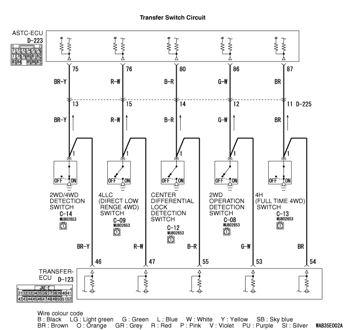
If the transfer gear is engaged, a relevant switch is turned on. When the switch is turned
on, the current from the ASTC-ECU is earthed.
|
|
|
DIAGNOSIS CODE SET CONDITIONS
|
|
|
Diagnosis code No. 75 is set when ASTC-ECU judges that there is any abnormality with the
2WD/4WD detection switch state, 4LLC (direct low range 4WD) switch state, centre differential
lock detection switch state, 2WD operation switch state, and 4H (full time 4WD) switch state
which are inputted to ASTC-ECU.
|
|
|
The most likely causes for these diagnosis codes to set are:
|
|
|
- Damaged wiring harness or connector
- Malfunction of the 2WD/4WD detection switch
- Malfunction of the 4LLC (direct low range 4WD) switch
- Malfunction of the centre differential lock detection switch
- Malfunction of the 2WD operation switch
- Malfunction of the 4H (full time 4WD) switch
- Malfunction of the ASTC-ECU
|
|
|
STEP 1. M.U.T.-III CAN bus diagnostics
|
|
|
| caution |
Before connecting or disconnecting the M.U.T.-III, turn the ignition
switch to the "LOCK" (OFF) position.
|
|
|
|
(1)Connect M.U.T.-III to the 16-pin diagnosis connector.
|
|
|
(2)Turn the ignition switch to the "ON" position.
|
|
|
(3)Diagnose the CAN bus line.
|
|
|
(4)Turn the ignition switch to the "LOCK" (OFF) position.
|
|
|
Q.
Is the check result normal?
|
|
|
 Go to Step 3. Go to Step 3.
|
|
|
|
|
|
 Repair the CAN bus line (Refer to GROUP 54D, CAN bus line Diagnostic flow ).
Then go to Step 2. Repair the CAN bus line (Refer to GROUP 54D, CAN bus line Diagnostic flow ).
Then go to Step 2.
|
|
|
|
|
|
STEP 2. Check whether the diagnosis code is reset.
|
|
|
| caution |
Before connecting or disconnecting the M.U.T.-III, turn the ignition
switch to the "LOCK" (OFF) position.
|
|
|
|
(1)Turn the ignition switch to the "ON" position.
|
|
|
(2)Erase the diagnosis code.
|
|
|
(3)Turn the ignition switch to the "LOCK" (OFF) position.
|
|
|
(4)Turn the ignition switch to the "ON" position.
|
|
|
(5)Change all transfer modes.
| note |
For automatic transmission vehicle some transfer mode requires neutral position.
|
|
|
|
(6)Check if the diagnosis code is set.
|
|
|
(7)Turn the ignition switch to the "LOCK" (OFF) position.
|
|
|
Go to Step 3.
|
|
|
|
|
|
The procedure is complete.
|
|
|
|
|
|
STEP 3. Check for diagnosis codes of other systems.
|
|
|
Check if a diagnosis code is set by the transfer-ECU.
|
|
|
Diagnose the transfer-ECU <Refer to GROUP 22A, Diagnosis code chart (SS4II) .>.
|
|
|
|
|
|
Go to Step 4.
|
|
|
|
|
|
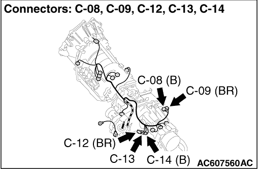
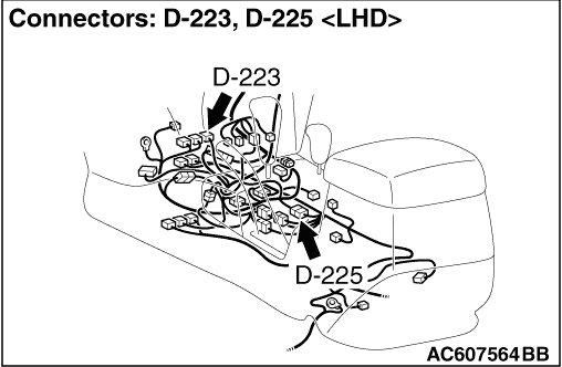
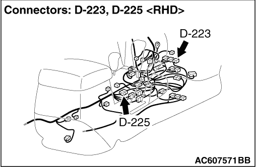
STEP 4. Check D-223 ASTC-ECU connector, D-225 intermediate connector,
C-14 2WD/4WD detection switch connector, C-09 4LLC (direct low range 4WD) switch connector,
C-12 centre differential lock detection switch connector, C-08 2WD operation switch connector and
C-13 4H (full time 4WD) switch connector for loose, corroded or damaged terminals, or terminals
pushed back in the connector.
|
|
|
Q.
Is the check result normal?
|
|
|
Go to Step 5.
|
|
|
|
|
|
Repair or replace the damaged component(s). Then go to Step 11.
|
|
|
|
|
|
STEP 5. Check the wiring harness from the D-223 ASTC-ECU connector
terminal No.75 to C-14 2WD/4WD detection switch connector terminal No.1.
|
|
|
Check for open circuit and short to power supply and earth.
|
|
|
Q.
Is the check result normal?
|
|
|
Go to Step 6.
|
|
|
|
|
|
Repair the wiring harness. Then go to Step 11.
|
|
|
|
|
|
STEP 6. Check the wiring harness from the D-223 ASTC-ECU connector
terminal No.76 to C-09 4LLC (direct low range 4WD) switch connector terminal No.1.
|
|
|
Check for open circuit and short to power supply and earth.
|
|
|
Q.
Is the check result normal?
|
|
|
Go to Step 7.
|
|
|
|
|
|
Repair the wiring harness. Then go to Step 11.
|
|
|
|
|
|
STEP 7. Check the wiring harness from the D-223 ASTC-ECU connector
terminal No.80 to C-12 centre differential lock switch connector terminal No.1.
|
|
|
Check for open circuit and short to power supply and earth.
|
|
|
Q.
Is the check result normal?
|
|
|
Go to Step 8.
|
|
|
|
|
|
Repair the wiring harness. Then go to Step 11.
|
|
|
|
|
|
STEP 8. Check the wiring harness from the D-223 ASTC-ECU connector
terminal No.86 to C-08 2WD operation detection switch connector terminal No.1.
|
|
|
Check for open circuit and short to power supply and earth.
|
|
|
Q.
Is the check result normal?
|
|
|
Go to Step 9.
|
|
|
|
|
|
Repair the wiring harness. Then go to Step 11.
|
|
|
|
|
|
STEP 9. Check the wiring harness from the D-223 ASTC-ECU connector
terminal No.87 to C-13 4H (full time 4WD) switch connector terminal No.1.
|
|
|
Check for open circuit and short to power supply and earth.
|
|
|
Q.
Is the check result normal?
|
|
|
Go to Step 10.
|
|
|
|
|
|
Repair the wiring harness. Then go to Step 11.
|
|
|
|
|
|
STEP 10. Check whether the diagnosis code is reset.
|
|
|
(1)Turn the ignition switch to the "ON" position.
|
|
|
(2)Erase the diagnosis code.
|
|
|
(3)Turn the ignition switch to the "LOCK" (OFF) position.
|
|
|
(4)Turn the ignition switch to the "ON" position.
|
|
|
(5)Change all transfer modes.
| note |
For automatic transmission vehicle some transfer mode requires neutral position.
|
|
|
|
(6)Check if the diagnosis code is set.
|
|
|
(7)Turn the ignition switch to the "LOCK" (OFF) position.
|
|
|
Replace the ASTC-ECU. Then go to Step 11.
|
|
|
|
|
|
It can be assumed that this malfunction is intermittent. Refer to GROUP 00, How
to Use Troubleshooting/Inspection Service Points - How to Cope with Intermittent
Malfunction .
|
|
|
|
|
|
STEP 11. Check whether the diagnosis code is reset.
|
|
|
(1)Turn the ignition switch to the "ON" position.
|
|
|
(2)Erase the diagnosis code.
|
|
|
(3)Turn the ignition switch to the "LOCK" (OFF) position.
|
|
|
(4)Turn the ignition switch to the "ON" position.
|
|
|
(5)Change all transfer modes.
| note |
For automatic transmission vehicle some transfer mode requires neutral position.
|
|
|
|
(6)Check if the diagnosis code is set.
|
|
|
(7)Turn the ignition switch to the "LOCK" (OFF) position.
|
|
|
Repeat the troubleshooting from Step 1.
|
|
|
|
|
|
The procedure is complete.
|
|
|
|