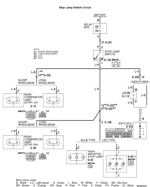
Code No.33: Stop
Lamp Switch System
|
|
| caution |
If there is any problem in
the CAN bus lines, an incorrect diagnosis code may be set. Diagnose the CAN bus lines before
the diagnosis codes (Refer to GROUP 54D, CAN bus-line diagnostic flow  ). ).
|
|
|
|
ASTC-ECU monitors whether the stop lamp switch is "ON" or "OFF."
|
|
|
ASTC-ECU monitors whether the stop lamp switch is "ON" or "OFF."
|
|
|
DIAGNOSIS CODE SET CONDITIONS
|
|
|
This diagnosis code will be set if the ASTC-ECU judges that the vehicle speed is 15 km/h
or more with the stop lamp switch "ON" continuously for 15 minutes or more.
|
|
|
- Malfunction of the stop lamp switch
- Incorrect adjustment of the stop lamp switch
- Blown stop lamp bulb
- Improper modification of the stop lamp
- Damaged wiring harness or connector
- Malfunction of the ASTC-ECU
|
|
|
STEP 1. M.U.T.-III CAN bus diagnostics
|
|
|
| caution |
Before connecting or disconnecting the M.U.T.-III, turn the ignition
switch to the "LOCK" (OFF) position.
|
|
|
|
(1)Connect M.U.T.-III to the 16-pin diagnosis connector.
|
|
|
(2)Turn the ignition switch to the "ON" position.
|
|
|
(3)Diagnose the CAN bus line.
|
|
|
(4)Turn the ignition switch to the "LOCK" (OFF) position.
|
|
|
Q.
Is the check result normal?
|
|
|
 Go to Step 3. Go to Step 3.
|
|
|
|
|
|
 Repair the CAN bus lines (Refer to GROUP 54D, CAN bus line Diagnostic flow ).
On completion, go to Step 2. Repair the CAN bus lines (Refer to GROUP 54D, CAN bus line Diagnostic flow ).
On completion, go to Step 2.
|
|
|
|
|
|
STEP 2. Check whether the diagnosis code is reset.
|
|
|
| caution |
Before connecting or disconnecting the M.U.T.-III, turn the ignition
switch to the "LOCK" (OFF) position.
|
|
|
|
(1)Turn the ignition switch to the "ON" position.
|
|
|
(2)Erase the diagnosis code.
|
|
|
(3)Turn the ignition switch to the "LOCK" (OFF) position.
|
|
|
(4)Turn the ignition switch to the "ON" position.
|
|
|
(5)Disconnect the M.U.T.-III.
|
|
|
(6)Drive the vehicle more than 15 minutes at the speed exceeds 15 km/h to
judge the stop lamp switch to the ASTC-ECU.
|
|
|
(7)Connect the M.U.T.-III.
|
|
|
(8)Check if the diagnosis code is set.
|
|
|
(9)Turn the ignition switch to the "LOCK" (OFF) position.
|
|
|
Go to Step 3.
|
|
|
|
|
|
The procedure is complete.
|
|
|
|
|
|
STEP 3. Stop lamp operation check
|
|
|
Check the stop lamp operation when the brake pedal is depressed. Check that the stop lamp
illuminates when the brake pedal is depressed and that it goes out when the brake pedal is released.
|
|
|
OK:
When the brake pedal is released: OFF
When the brake pedal is depressed: ON
|
|
|
Q.
Is the check result normal?
|
|
|
Go to Step 17.
|
|
|
|
|
|
NO <All of rear combination lamp (LH, RH) and high-mounted stop lamp are illuminating
and not extinguished.> : Go to Step 4. : Go to Step 4.
|
|
|
|
|
|
NO <None of rear combination lamp (LH, RH) and high-mounted stop lamp illuminates.> : Go to Step 9.
|
|
|
|
|
|
NO <One of the rear combination lamp (LH, RH) and high-mounted stop lamp illuminates
or goes out normally.> : Go to Step 17.
|
|
|
|
|
|
STEP 4. Check for stop lamp switch installation
|
|
|
Refer to GROUP 35A -
On-vehicle Service .
|
|
|
Q.
Is the check result normal?
|
|
|
Go to Step 5.
|
|
|
|
|
|
Install the stop lamp switch correctly (Refer to GROUP 35A -
On-vehicle
Service ). Then go to Step 20.
|
|
|
|
|
|
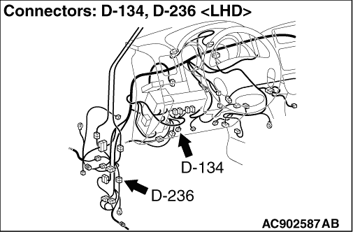
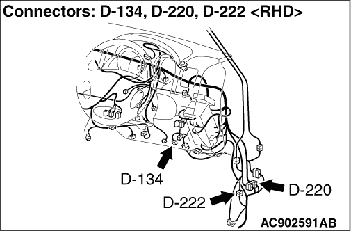
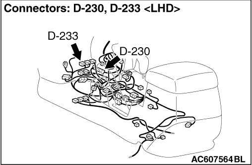
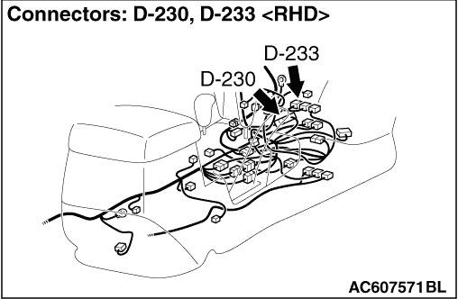
STEP 5. Connector check: D-134 stop lamp switch connector, D-233 ASTC-ECU
connector
|
|
|
Q.
Is the check result normal?
|
|
|
Go to Step 6.
|
|
|
|
|
|
Repair the defective connector.
|
|
|
|
|
|
STEP 6. Stop lamp switch continuity check
|
|
|
(1)Remove the stop lamp switch (Refer to GROUP 35A -Brake Pedal ).
|
|
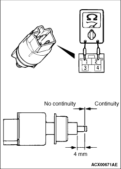
(2)Connect the circuit tester (Ω
range) to the stop lamp switch connector terminals
No.1 and 2.
(3)When no continuity is detected with the plunger pressed from the edge of the outer
case by the dimension shown in the figure and when continuity is detected with the plunger released,
the stop lamp switch is in good condition.
Q.
Is the check result normal?
Go to Step 7.
Replace the stop lamp switch (Refer to GROUP 35A -
Brake Pedal .)
Then go to Step 20.
|
|
|
STEP 7. Voltage measurement at the D-233 ASTC-ECU connector
|
|
|
(1)Disconnect the D-233 ASTC-ECU connector and D-134 stop lamp switch connector, and
measure at the D-233 ASTC-ECU connector wiring harness side.
|
|
|
(2)Measure the voltage between the terminal No.19 and the body earth.
OK: Approximately 1 V or less
|
|
|
Q.
Is the check result normal?
|
|
|
Go to Step 19.
|
|
|
|
|
|
Go to Step 8.
|
|
|
|
|
|
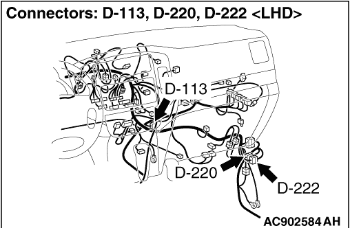
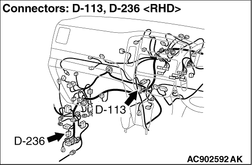
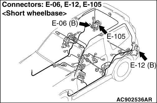
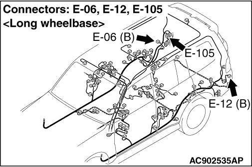
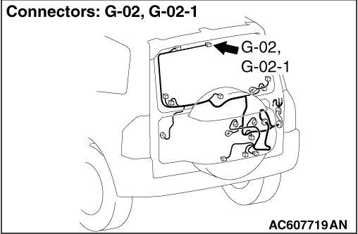
STEP 8. Connector check: D-233 ASTC-ECU connector, D-230 intermediate
connector, D-222 intermediate connector <LHD>, D-220 intermediate connector <RHD>, D-236 intermediate
connector, E-105 intermediate connector, D-113 joint connector <3200>, E-06 rear combination
lamp (STOP: RH) connector, E-12 rear combination lamp (STOP: LH) connector, G-02 high-mount
stop lamp connector <bulb type>, G-02-1 high-mount stop lamp connector <LED type>
|
|
|
Q.
Is the check result normal?
|
|
|
A short to power supply has occurred in the wiring harness between D-134 stop
lamp switch connector terminal No.1 and E-06 rear combination lamp (STOP: RH) connector terminal
No.2, E-12 rear combination lamp (STOP: LH) connector terminal No.2, or G-02 high-mount stop
lamp connector terminal No.2 <bulb type>, G-02-1 high-mount stop lamp connector terminal
No.2 <LED type>, therefore, repair it.
|
|
|
|
|
|
Repair the defective connector.
|
|
|
|
|
|
STEP 9. Check the fuse No.16.
|
|
|
Q.
Is the check result normal?
|
|
|
Go to Step 12.
|
|
|
|
|
|
Go to Step 10.
|
|
|
|
|
|
STEP 10. Connector check: D-134 stop lamp switch connector, D-233
ASTC-ECU connector, D-230 intermediate connector, D-222 intermediate connector <LHD>, D-220
intermediate connector <RHD>, D-236 intermediate connector, D-113 joint connector <3200>,
E-105 intermediate connector, E-06 rear combination lamp (STOP: RH) connector, E-12 rear combination
lamp (STOP: LH) connector, G-02 high-mount stop lamp connector <bulb type>, G-02-1 high-mount
stop lamp connector <LED type>
|
|
|
Q.
Is the check result normal?
|
|
|
Go to Step 11.
|
|
|
|
|
|
Repair the defective connector.
|
|
|
|
|
|
STEP 11. Resistance measurement at D-134 stop lamp switch connector
|
|
|
(1)Remove the D-134 stop lamp switch connector and fuse No.16, and measure at the
wiring harness side of D-134 stop lamp switch connector.
|
|
|
(2)Resistance between the terminal No.2 and the body earth.
OK: No continuity
|
|
|
Q.
Is the check result normal?
|
|
|
A short to earth has occurred in the wiring harness between D-134 stop lamp switch
connector terminal No.2 and fuse No.16, therefore, repair it.
|
|
|
|
|
|
Check if a short to earth has occurred in the wiring harness between D-134 stop
lamp switch connector terminal No.1 and E-06 rear combination lamp (STOP: RH) connector terminal
No.2, E-12 rear combination lamp (STOP: LH) connector terminal No.2, or G-02 high-mount stop
lamp connector terminal No.2 <bulb type>, G-02-1 high-mount stop lamp connector terminal
No.2 <LED type>. If a short to earth has occurred, repair it and replace fuse No.16. If
not, replace fuse No.16.Then go to Step 20.
|
|
|
|
|
|
STEP 12. Check for stop lamp switch installation
|
|
|
Refer to GROUP 35A -
On-vehicle Service .
|
|
|
Q.
Is the check result normal?
|
|
|
Go to Step 13.
|
|
|
|
|
|
Install the stop lamp switch correctly (Refer to GROUP 35A -
On-vehicle
Service ). Then go to Step 20.
|
|
|
|
|
|
STEP 13. Connector check: D-134 stop lamp switch connector
|
|
|
Q.
Is the check result normal?
|
|
|
Go to Step 14.
|
|
|
|
|
|
Repair the defective connector.
|
|
|
|
|
|
STEP 14. Stop lamp switch continuity check
|
|
|
(1)Remove the stop lamp switch (Refer to GROUP 35A -Brake Pedal ).
|
|
(2)Connect the circuit tester (Ω
range) to the stop lamp switch connector terminals
No.1 and 2.
(3)When no continuity is detected with the plunger pressed from the edge of the outer
case by the dimension shown in the figure and when continuity is detected with the plunger released,
the stop lamp switch is in good condition.
Q.
Is the check result normal?
Go to Step 15.
Replace the stop lamp switch (Refer to GROUP 35A -
Brake Pedal .)
Then go to Step 20.
|
|
|
STEP 15. Resistance measurement at D-134 stop lamp switch connector
|
|
|
(1)Remove the D-134 stop lamp switch connector and fuse No.16, and measure at the
wiring harness side of D-134 stop lamp switch connector.
|
|
|
(2)Resistance between the terminal No.2 and the fuse No.16.
OK: Continuity exists (2 Ω
or less)
|
|
|
Q.
Is the check result normal?
|
|
|
Go to Step 16.
|
|
|
|
|
|
Repair the harness between D-134 stop lamp switch connector and fuse No.16.
|
|
|
|
|
|
STEP 16. Resistance measurement at D-134 stop lamp switch connector
|
|
|
(1)Remove the D-134 stop lamp switch connector, D-222 intermediate connector <LHD>,
D-220 intermediate connector <RHD>, D-236 intermediate connector and E-105 intermediate
connector, and measure at the wiring harness side of D-134 stop lamp switch connector.
|
|
|
(2)Resistance between the terminal No.1 and the body earth.
- Between D-134 stop lamp switch connector terminal No.1 and D-222 intermediate
connector terminal No.12 or No.6 <LHD>, D-220 intermediate connector terminal No.12 or
No.6 <RHD>
- Between D-134 stop lamp switch connector terminal No.1 and D-236 intermediate connector
terminal No.1 <LHD>, D-236 intermediate connector terminal No.13 <RHD>
- Between D-134 stop lamp switch connector terminal No.1 and E-105 intermediate connector
terminal No.2
OK: Continuity exists (2 Ω
or less)
|
|
|
Q.
Is the check result normal?
|
|
|
Go to Step 19.
|
|
|
|
|
|
Repair the harness between D-134 stop lamp switch connector and D-222 intermediate
connector <LHD>, D-220 intermediate connector <RHD>, D-236 intermediate connector and
E-105 intermediate connector
|
|
|
|
|
|
STEP 17. Connector check: D-233 ASTC-ECU connector, D-230 intermediate
connector, D-113 joint connector <3200>
|
|
|
Q.
Is the check result normal?
|
|
|
Go to Step 18.
|
|
|
|
|
|
Repair the defective connector.
|
|
|
|
|
|
STEP 18. Voltage measurement at D-233 ASTC-ECU connector
|
|
|
(1)Remove the D-233 ASTC-ECU connector and measure at the wiring harness side.
|
|
|
(2)Measure the voltage between the terminal No.19 and the body earth.
OK:
When the brake pedal is released: Approximately 1 V or less
When the brake pedal is depressed: Approximately system voltage
|
|
|
Q.
Is the check result normal?
|
|
|
Replace the ASTC-ECU (Refer to ). Then go to Step
20.
|
|
|
|
|
|
Repair the harness between the D-134 stop lamp switch connector terminal No.1
and D-233 ASTC-ECU connector terminal No.19.
|
|
|
|
|
|
STEP 19. Check whether the diagnosis code is reset.
|
|
|
Check again if the diagnosis code is set.
|
|
|
(1)Turn the ignition switch to the "ON" position.
|
|
|
(2)Erase the diagnosis code.
|
|
|
(3)Turn the ignition switch to the "LOCK" (OFF) position.
|
|
|
(4)Turn the ignition switch to the "ON" position.
|
|
|
(5)Disconnect the M.U.T.-III.
|
|
|
(6)Drive the vehicle more than 15 minutes at the speed exceeds 15 km/h to
judge the stop lamp switch to the ASTC-ECU.
|
|
|
(7)Check if the diagnosis code is reset.
|
|
|
(8)Turn the ignition switch to the "LOCK" (OFF) position.
|
|
|
Replace the ASTC-ECU (Refer to ). Then go to Step
20.
|
|
|
|
|
|
It can be assumed that this malfunction is intermittent. Refer to GROUP 00, How
to Use Troubleshooting/Inspection Service Points -
How to Cope with Intermittent
Malfunction .
|
|
|
|
|
|
STEP 20. Check whether the diagnosis code is reset.
|
|
|
(1)Turn the ignition switch to the "ON" position.
|
|
|
(2)Erase the diagnosis code.
|
|
|
(3)Turn the ignition switch to the "LOCK" (OFF) position.
|
|
|
(4)Turn the ignition switch to the "ON" position.
|
|
|
(5)Disconnect the M.U.T.-III.
|
|
|
(6)Drive the vehicle more than 15 minutes at the speed exceeds 15 km/h to
judge the stop lamp switch to the ASTC-ECU.
|
|
|
(7)Check if the diagnosis code is set.
|
|
|
(8)Turn the ignition switch to the "LOCK" (OFF) position.
|
|
|
Return to Step 1.
|
|
|
|
|
|
The procedure is complete.
|
|
|
|