Code No.41: Control
Solenoid Valve (FR) System
Code No.42: Control Solenoid Valve (FL) System
Code
No.43: Control Solenoid Valve (RR) System
Code No.44: Control Solenoid Valve (RL) System
Code
No.45: Switch Solenoid Valve (SA1) System
Code No.46: Switch Solenoid Valve (SA2) System
Code
No.47: Switch Solenoid Valve (SA3) System
Code No.48: Switch Solenoid Valve (STR) System
|
|
| caution |
If there is any problem in
the CAN bus lines, an incorrect diagnosis code may be set. Diagnose the CAN bus lines before
the diagnosis codes (Refer to GROUP 54D, CAN bus-line diagnostic flow  ). ).
|
|
|
|
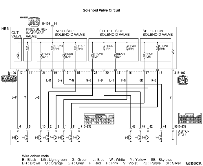
HBB is supplied with power for drive of each solenoid valve from the fusible link No.
31 by turning ON the valve relay, and the drive of each solenoid valve is controlled by ASTC-ECU.
|
|
|
DIAGNOSIS CODE SET CONDITIONS
|
|
|
Diagnosis codes No. 41, 42, 43, 44, 45, 46, 47, and 48 are set in the following cases;
|
|
|
- Although the solenoid valve is turned ON by ASTC-ECU, ASTC-ECU not judges
that current flows through the solenoid valve.
- Although the solenoid valve is turned OFF by ASTC-ECU, ASTC-ECU judges that current
continues to flow through the solenoid valve.
|
|
|
The most likely causes for these diagnosis codes to set are:
|
|
|
- Damaged wiring harness or connector
- Malfunction of the solenoid valve
- Malfunction of the ASTC-ECU
|
|
|
STEP 1. M.U.T.-III CAN bus diagnostics
|
|
|
| caution |
Before connecting or disconnecting the M.U.T.-III, turn the ignition
switch to the "LOCK" (OFF) position.
|
|
|
|
(1)Connect M.U.T.-III to the 16-pin diagnosis connector.
|
|
|
(2)Turn the ignition switch to the "ON" position.
|
|
|
(3)Diagnose the CAN bus line.
|
|
|
(4)Turn the ignition switch to the "LOCK" (OFF) position.
|
|
|
Q.
Is the check result normal?
|
|
|
 Go to Step 3. Go to Step 3.
|
|
|
|
|
|
 Repair the CAN bus line (Refer to GROUP 54D, CAN bus line Diagnostic flow ).
Then go to Step 2. Repair the CAN bus line (Refer to GROUP 54D, CAN bus line Diagnostic flow ).
Then go to Step 2.
|
|
|
|
|
|
STEP 2. Check whether the diagnosis code is reset.
|
|
|
| caution |
Before connecting or disconnecting the M.U.T.-III, turn the ignition
switch to the "LOCK" (OFF) position.
|
|
|
|
(1)Turn the ignition switch to the "ON" position.
|
|
|
(2)Erase the diagnosis code.
|
|
|
(3)Turn the ignition switch to the "LOCK" (OFF) position.
|
|
|
(4)Turn the ignition switch to the "ON" position.
|
|
|
(5)Disconnect the M.U.T.-III.
|
|
|
(6)Drive the vehicle more at the speeds exceeds 10 km/h to execute the valve initial
check.
|
|
|
(7)Check if the diagnosis code is set.
|
|
|
(8)Turn the ignition switch to the "LOCK" (OFF) position.
|
|
|
Q.
Is code No.41, 42, 43, 44, 45, 46, 47 or 48 set?
|
|
|
Go to Step 3.
|
|
|
|
|
|
The procedure is complete.
|
|
|
|
|
|
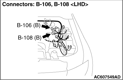
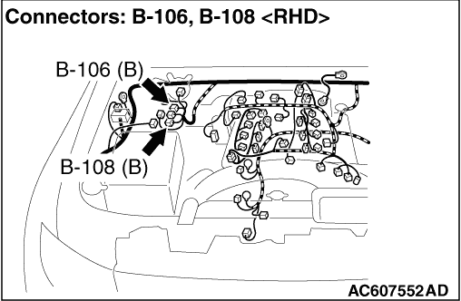
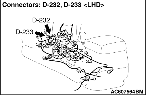
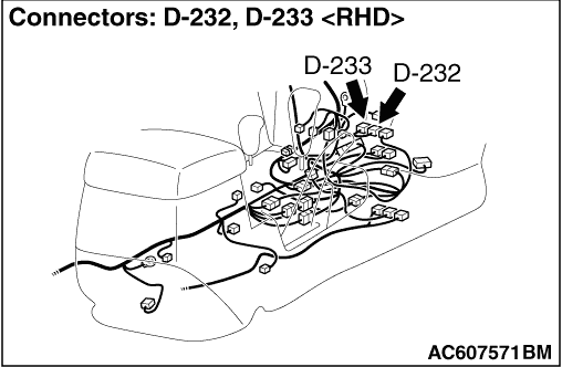
STEP 3. Check B-106 HBB connector, B-107 HBB connector, B-108 HBB
connector, D-232 ASTC-ECU connector, D-233 ASTC-ECU connector for loose, corroded or damaged
terminals, or terminals pushed back in the connector.
|
|
|
Q.
Is the check result normal?
|
|
|
Go to Step 4.
|
|
|
|
|
|
Repair or replace the damaged component(s). Then go to Step 8.
|
|
|
|
|
|
STEP 4. Resistance measurement at B-106 HBB connector and B-108 HBB
connector.
|
|
|
Measure the resistance between the terminals of each solenoid valve at B-106 HBB connector
and B-108 HBB connector (equipment side) (Refer to ).
|
|
|
Q.
Is the check result normal?
|
|
|
Go to Step 5.
|
|
|
|
|
|
Replace the HBB. Then go to Step 8.
|
|
|
|
|
|
STEP 5. Check the harness wires between B-106 HBB connector and D-232
ASTC-ECU connector, D-233 ASTC-ECU connector.
|
|
|
Check the wiring harnesses between the following terminals.
|
|
|
Code No.41
- B-106 HBB connector terminal No.19 - D-232 ASTC-ECU connector terminal
No.42
- B-106 HBB connector terminal No.20 - D-232 ASTC-ECU connector terminal
No.43
|
|
|
Code No.42
- B-106 HBB connector terminal No.21 - D-233 ASTC-ECU connector terminal
No.10
- B-106 HBB connector terminal No.22 - D-233 ASTC-ECU connector terminal
No.3
|
|
|
Code No.43
- B-106 HBB connector terminal No.15 - D-233 ASTC-ECU connector terminal
No.2
- B-106 HBB connector terminal No.16 - D-233 ASTC-ECU connector terminal
No.1
|
|
|
Code No.44
- B-106 HBB connector terminal No.13 - D-232 ASTC-ECU connector terminal
No.44
- B-106 HBB connector terminal No.14 - D-232 ASTC-ECU connector terminal
No.45
|
|
|
Code No.45
- B-106 HBB connector terminal No.18 - D-233 ASTC-ECU connector terminal
No.7
|
|
|
Code No.46
- B-106 HBB connector terminal No.17 - D-233 ASTC-ECU connector terminal
No.8
|
|
|
Code No.47
- B-106 HBB connector terminal No.12 - D-233 ASTC-ECU connector terminal
No.6
|
|
|
Code No.48
- B-106 HBB connector terminal No.11 - D-233 ASTC-ECU connector terminal
No.5
|
|
|
Q.
Is the check result normal?
|
|
|
Go to Step 6.
|
|
|
|
|
|
Repair the wiring harness. Then go to Step 8.
|
|
|
|
|
|
STEP 6. Resistance measurement at B-107 HBB connector and D-232 ASTC-ECU
connector.
|
|
|
(1)Disconnect the D-107 HBB connector and D-232 ASTC-ECU connector.
|
|
|
(2)Measure the resistance between the B-107 HBB connector terminal No.3 and D-232
ASTC-ECU connector terminal No.55.
OK: Continuity exists (2 Ω or less)
|
|
|
Q.
Is the check result normal?
|
|
|
Go to Step 7.
|
|
|
|
|
|
Repair the wiring harness. Then go to Step 8.
|
|
|
|
|
|
STEP 7. Check whether the diagnosis code is reset.
|
|
|
Check again if the diagnosis code is set.
|
|
|
(1)Turn the ignition switch to the "ON" position.
|
|
|
(2)Erase the diagnosis code.
|
|
|
(3)Turn the ignition switch to the "LOCK" (OFF) position.
|
|
|
(4)Turn the ignition switch to the "ON" position.
|
|
|
(5)Disconnect the M.U.T.-III.
|
|
|
(6)Drive the vehicle more at the speeds exceeds 10 km/h to execute the valve initial
check.
|
|
|
(7)Check if the diagnosis code is reset.
|
|
|
(8)Turn the ignition switch to the "LOCK" (OFF) position.
|
|
|
Q.
Is code No.41, 42, 43, 44, 45, 46, 47 or 48 set?
|
|
|
Replace the ASTC-ECU. Then go to Step 8.
|
|
|
|
|
|
It can be assumed that this malfunction is intermittent. Refer to GROUP 00, How
to Use Troubleshooting/Inspection Service Points - How to Cope with Intermittent
Malfunction .
|
|
|
|
|
|
STEP 8. Check whether the diagnosis code is reset.
|
|
|
(1)Turn the ignition switch to the "ON" position.
|
|
|
(2)Erase the diagnosis code.
|
|
|
(3)Turn the ignition switch to the "LOCK" (OFF) position.
|
|
|
(4)Turn the ignition switch to the "ON" position.
|
|
|
(5)Disconnect the M.U.T.-III.
|
|
|
(6)Drive the vehicle more at the speeds exceeds 10 km/h to execute the valve initial
check.
|
|
|
(7)Check if the diagnosis code is set.
|
|
|
(8)Turn the ignition switch to the "LOCK" (OFF) position.
|
|
|
Q.
Is code No.41, 42, 43, 44, 45, 46, 47 or 48 set?
|
|
|
Repeat the troubleshooting from Step 1.
|
|
|
|
|
|
The procedure is complete.
|
|
|
|