|
|
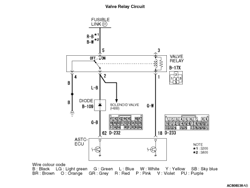
HBB is supplied with power for drive of each solenoid valve from the fusible link No.
31 by turning ON the valve relay, and the drive of each solenoid valve is controlled by ASTC-ECU.
|
|
|
Diagnosis code No. 52 is set if ASTC-ECU judges that power for the solenoid valve is not
supplied when ASTC-ECU turns ON the valve relay.
|
|
|
The most likely causes for these diagnosis codes to set are:
|
|
|
- Damaged wiring harness or connector
- Malfunction of the valve relay
- Malfunction of the ASTC-ECU
|
|
|
(1)Connect M.U.T.-III to the 16-pin diagnosis connector.
|
|
|
(2)Turn the ignition switch to the "ON" position.
|
|
|
(3)Diagnose the CAN bus line.
|
|
|
(4)Turn the ignition switch to the "LOCK" (OFF) position.
|
|
|
Q.
Is the check result normal?
|
|
|
 Repair the CAN bus line (Refer to GROUP 54D, CAN bus line Diagnostic flow Repair the CAN bus line (Refer to GROUP 54D, CAN bus line Diagnostic flow  ).
Then go to Step 2. ).
Then go to Step 2.
|
|
|
|
|
|
(1)Turn the ignition switch to the "ON" position.
|
|
|
(2)Erase the diagnosis code.
|
|
|
(3)Turn the ignition switch to the "LOCK" (OFF) position.
|
|
|
(4)Turn the ignition switch to the "ON" position.
|
|
|
(5)Check if the diagnosis code is set.
|
|
|
(6)Turn the ignition switch to the "LOCK" (OFF) position.
|
|
|
The procedure is complete.
|
|
|
|
|
|
Q.
Is the check result normal?
|
|
|
Replace the valve relay. Then go to Step 10.
|
|
|
|
|
|
Q.
Is the check result normal?
|
|
|
Repair or replace the damaged component(s). Then go to Step 10.
|
|
|
|
|
|
Check for open circuit to power supply.
|
|
|
Q.
Is the check result normal?
|
|
|
Repair the wiring harness. Then go to Step 10.
|
|
|
|
|
|
Check for open circuit or short to power supply.
|
|
|
Q.
Is the check result normal?
|
|
|
Repair the wiring harness. Then go to Step 10.
|
|
|
|
|
|
Check for open circuit or short to earth.
|
|
|
Q.
Is the check result normal?
|
|
|
Repair the wiring harness. Then go to Step 10.
|
|
|
|
|
|
Q.
Is the check result normal?
|
|
|
Repair the wiring harness. Then go to Step 10.
|
|
|
|
|
|
Check again if the diagnosis code is set.
|
|
|
(1)Turn the ignition switch to the "ON" position.
|
|
|
(2)Erase the diagnosis code.
|
|
|
(3)Turn the ignition switch to the "LOCK" (OFF) position.
|
|
|
(4)Turn the ignition switch to the "ON" position.
|
|
|
(5)Check if the diagnosis code is reset.
|
|
|
(6)Turn the ignition switch to the "LOCK" (OFF) position.
|
|
|
 Replace the ASTC-ECU. Then go to Step 10. Replace the ASTC-ECU. Then go to Step 10.
|
|
|
|
|
|
It can be assumed that this malfunction is intermittent. Refer to GROUP 00, How
to Use Troubleshooting/Inspection Service Points - How to Cope with Intermittent
Malfunction .
|
|
|
|
|
|
(1)Turn the ignition switch to the "ON" position.
|
|
|
(2)Erase the diagnosis code.
|
|
|
(3)Turn the ignition switch to the "LOCK" (OFF) position.
|
|
|
(4)Turn the ignition switch to the "ON" position.
|
|
|
(5)Check if the diagnosis code is set.
|
|
|
(6)Turn the ignition switch to the "LOCK" (OFF) position.
|
|
|
Repeat the troubleshooting from Step 1.
|
|
|
|
|
|
The procedure is complete.
|
|
|
|