Code No.61: Master
Cylinder Pressure Sensor System
|
|
| caution |
If there is any problem in
the CAN bus lines, an incorrect diagnosis code may be set. Diagnose the CAN bus lines before
the diagnosis codes (Refer to GROUP 54D, CAN bus-line diagnostic flow  ). ).
|
|
|
|
HBB, which is provided with the master cylinder pressure sensor, converts the master cylinder
pressure input from the brake pedal into voltage value, and outputs it to ASTC-ECU.
|
|
|
DIAGNOSIS CODE SET CONDITIONS
|
|
|
Diagnosis code No. 61 is set in the following cases;
|
|
|
- Abnormal rise or drop of input voltage
- Abnormal rise or drop of output voltage
- When the pressure value does not vary while the stop lamp switch signal is ON.
- When the pressure value is outputted while the stop lamp switch signal is OFF.
- When a steady pressure value is always outputted during driving.
|
|
|
The most likely causes for these diagnosis codes to set are:
|
|
|
- Damaged wiring harness or connector
- Malfunction of the master cylinder pressure sensor
- Malfunction of the ASTC-ECU
- Incorrect adjustment of the stop lamp switch
- Malfunction of the stop lamp switch
- Malfunction of brake pedal
- Malfunction of the HBB
|
|
|
STEP 1. M.U.T.-III CAN bus diagnostics
|
|
|
| caution |
Before connecting or disconnecting the M.U.T.-III, turn the ignition
switch to the "LOCK" (OFF) position.
|
|
|
|
(1)Connect M.U.T.-III to the 16-pin diagnosis connector.
|
|
|
(2)Turn the ignition switch to the "ON" position.
|
|
|
(3)Diagnose the CAN bus line.
|
|
|
(4)Turn the ignition switch to the "LOCK" (OFF) position.
|
|
|
Q.
Is the check result normal?
|
|
|
 Go to Step 3. Go to Step 3.
|
|
|
|
|
|
 Repair the CAN bus line (Refer to GROUP 54D, CAN bus line Diagnostic flow ).
Then go to Step 2. Repair the CAN bus line (Refer to GROUP 54D, CAN bus line Diagnostic flow ).
Then go to Step 2.
|
|
|
|
|
|
STEP 2. Check whether the diagnosis code is reset.
|
|
|
| caution |
Before connecting or disconnecting the M.U.T.-III, turn the ignition
switch to the "LOCK" (OFF) position.
|
|
|
|
(1)Turn the ignition switch to the "ON" position.
|
|
|
(2)Erase the diagnosis code.
|
|
|
(3)Turn the ignition switch to the "LOCK" (OFF) position.
|
|
|
(4)Turn the ignition switch to the "ON" position.
|
|
|
(5)Disconnect the M.U.T.-III.
|
|
|
(6)Drive the vehicle more than 60 seconds at the speed exceeds 10 km/h. Stop
the vehicle by braking from the speed exceeds 40 km/h.
|
|
|
(7)Check if the diagnosis code is set.
|
|
|
(8)Turn the ignition switch to the "LOCK" (OFF) position.
|
|
|
Go to Step 3.
|
|
|
|
|
|
The procedure is complete.
|
|
|
|
|
|
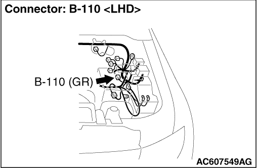
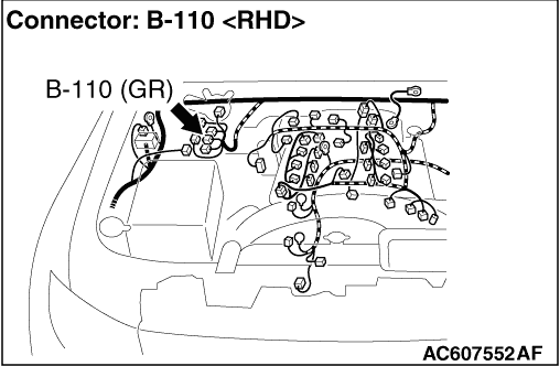
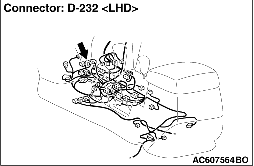
STEP 3. Check B-110 pressure sensor connector and D-232 ASTC-ECU connector
for loose, corroded or damaged terminals, or terminals pushed back in the connector.
|
|
|
Q.
Is the check result normal?
|
|
|
Go to Step 4.
|
|
|
|
|
|
Repair or replace the damaged component(s). Then go to Step 13.
|
|
|
|
|
|
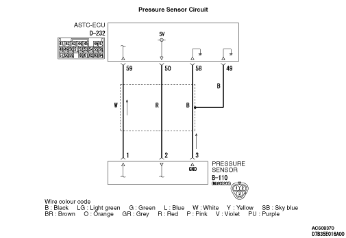
STEP 4. Check the power supply circuit at B-110 pressure sensor connector.
|
|
|
(1)Do not disconnect B-110 pressure sensor connector.
|
|
|
(2)Turn the ignition switch to the "ON" position.
|
|
|
(3)Measure voltage between terminal No.2 and earth.
OK: Approximately 5 V
|
|
|
Q.
Is the voltage approximately 5 volts?
|
|
|
Go to Step 7.
|
|
|
|
|
|
Go to Step 5.
|
|
|
|
|
|
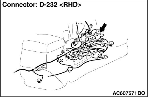
STEP 5. Check the D-232 ASTC-ECU connector.
|
|
|
(1)Disconnect the D-232 ASTC-ECU connector, and measure at the ASTC-ECU side.
|
|
|
(2)Turn the ignition switch to the "ON" position.
|
|
|
(3)Measure voltage between terminal No.50 and earth.
OK: Approximately 5 V
|
|
|
Q.
Is the check result normal?
|
|
|
Go to Step 6.
|
|
|
|
|
|
Replace the ASTC-ECU. Then go to Step 13.
|
|
|
|
|
|
STEP 6. Check the harness wire between B-110 pressure sensor connector
terminal No.2 and D-232 ASTC-ECU connector terminal No.50.
|
|
|
Q.
Is the check result normal?
|
|
|
It can be assumed that this malfunction is intermittent. Refer to GROUP 00, How
to Use Troubleshooting/Inspection Service Points - How to Cope with Intermittent
Malfunction .
|
|
|
|
|
|
Repair the wiring harness. Then go to Step 13.
|
|
|
|
|
|
STEP 7. Check the earth circuit at B-110 pressure sensor connector.
|
|
|
(1)Disconnect B-110 pressure sensor connector, and measure at the harness side.
|
|
|
(2)Measure the resistance between terminal No.3 and earth.
OK: Continuity exists (2 Ω or less)
|
|
|
Q.
Is the check result normal?
|
|
|
Go to Step 10.
|
|
|
|
|
|
Go to Step 8.
|
|
|
|
|
|
STEP 8. Check the D-232 ASTC-ECU connector.
|
|
|
(1)Disconnect the D-232 ASTC-ECU connector, and measure at the ASTC-ECU side.
|
|
|
(2)Measure the resistance between terminal No.49, No.58 and earth.
OK: Continuity exists (2 Ω or less)
|
|
|
Q.
Is the check result normal?
|
|
|
Go to Step 9.
|
|
|
|
|
|
Replace the ASTC-ECU. Then go to Step 13.
|
|
|
|
|
|
STEP 9. Check the harness wires between B-110 pressure sensor connector
terminal No.3 and D-232 ASTC-ECU connector terminal No.49, No.58.
|
|
|
Q.
Is the check result normal?
|
|
|
It can be assumed that this malfunction is intermittent. Refer to GROUP 00, How
to Use Troubleshooting/Inspection Service Points - How to Cope with Intermittent
Malfunction .
|
|
|
|
|
|
Repair the wiring harness. Then go to Step 13.
|
|
|
|
|
|
STEP 10. Check the B-110 pressure sensor connector.
|
|
|
(1)Do not disconnect the B-110 pressure sensor connector, and measure at the master
cylinder pressure sensor side.
|
|
|
(2)Turn the ignition switch to the "ON" position.
|
|
|
(3)Measure voltage between terminal No.1 and earth.
OK: 0.14 - 4.85 V
|
|
|
Q.
Is the check result normal?
|
|
|
Go to Step 11.
|
|
|
|
|
|
Replace the pressure sensor. Then go to Step 13.
|
|
|
|
|
|
STEP 11. Check the D-232 ASTC-ECU connector.
|
|
|
(1)Do not disconnect the D-232 ASTC-ECU connector, and measure at the harness side.
|
|
|
(2)Turn the ignition switch to the "ON" position.
|
|
|
(3)Measure voltage between terminal No.59 and earth.
OK: 0.14 - 4.85 V
|
|
|
Q.
Is the check result normal?
|
|
|
Replace the ASTC-ECU. Then go to Step 13.
|
|
|
|
|
|
Go to Step 12.
|
|
|
|
|
|
STEP 12. Check the harness wire between B-110 pressure sensor connector
terminal No.3 and D-232 ASTC-ECU connector terminal No.58.
|
|
|
Q.
Is the check result normal?
|
|
|
It can be assumed that this malfunction is intermittent. Refer to GROUP 00, How
to Use Troubleshooting/Inspection Service Points - How to Cope with Intermittent
Malfunction .
|
|
|
|
|
|
Repair the wiring harness. Then go to Step 13.
|
|
|
|
|
|
STEP 13. Check whether the diagnosis code is reset.
|
|
|
(1)Turn the ignition switch to the "ON" position.
|
|
|
(2)Erase the diagnosis code.
|
|
|
(3)Turn the ignition switch to the "LOCK" (OFF) position.
|
|
|
(4)Turn the ignition switch to the "ON" position.
|
|
|
(5)Check if the diagnosis code is set.
|
|
|
(6)Turn the ignition switch to the "LOCK" (OFF) position.
|
|
|
Repeat the troubleshooting from Step 1.
|
|
|
|
|
|
The procedure is complete.
|
|
|
|