Code No.63: G-sensor
Output Error
Code No.64: G-sensor Seizure
Code No.65: G-sensor Self-diagnosis
Error
Code No.76: G-sensor Error
Code No.71: Yaw Rate Sensor Self-diagnosis
Error
Code No.72: Yaw Rate Sensor 0-point Error
Code No.73: Yaw Rate Sensor
Output Error
Code No.77: Yaw Rate Sensor Error
|
|
| caution |
If there is any problem in
the CAN bus lines, an incorrect diagnosis code may be set. Diagnose the CAN bus lines before
the diagnosis codes (Refer to GROUP 54D, CAN bus-line diagnostic flow  ). ).
|
|
|
|
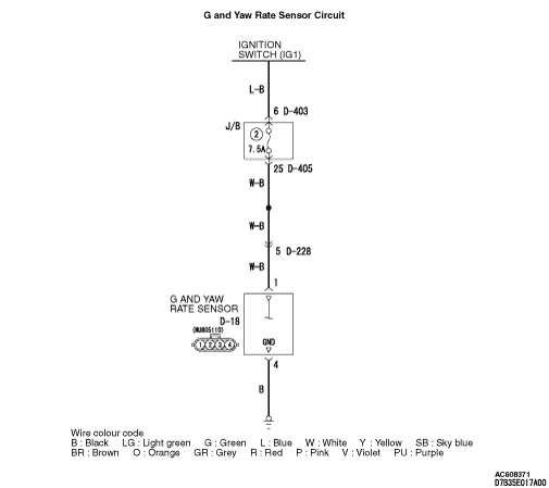
The ASTC-ECU gathers information regarding lateral and longitudinal gravities and yaw
rate, through the CAN bus line from the G and yaw rate sensor.
|
|
|
DIAGNOSIS CODE SET CONDITIONS
|
|
|
These diagnostic trouble codes will be set under the cases below.
|
|
|
Diagnosis code No.65, 71, 76
- When the G and yaw rate sensor is defective
|
|
|
Diagnosis code No.63, 64, 72 and 73
- When the output value from the G and yaw rate sensor is abnormal
|
|
|
| note |
Diagnosis codes No.76 and No.77 are set if a strong vibration is applied to the G and
yaw rate sensor right after the engine is started. However, they are set temporarily and it
is not a failure.
|
|
|
|
The most likely causes for these diagnosis codes to set are:
|
|
|
- Damaged wiring harness or connector
- Malfunction of the G and yaw rate sensor
- Malfunction of the ASTC-ECU
|
|
|
STEP 1. M.U.T.-III CAN bus diagnostics
|
|
|
| caution |
Before connecting or disconnecting the M.U.T.-III, turn the ignition
switch to the "LOCK" (OFF) position.
|
|
|
|
(1)Connect M.U.T.-III to the 16-pin diagnosis connector.
|
|
|
(2)Turn the ignition switch to the "ON" position.
|
|
|
(3)Diagnose the CAN bus line.
|
|
|
(4)Turn the ignition switch to the "LOCK" (OFF) position.
|
|
|
Q.
Is the check result normal?
|
|
|
 Go to Step 3. Go to Step 3.
|
|
|
|
|
|
 Repair the CAN bus line (Refer to GROUP 54D, CAN bus line Diagnostic flow ).
Then go to Step 2. Repair the CAN bus line (Refer to GROUP 54D, CAN bus line Diagnostic flow ).
Then go to Step 2.
|
|
|
|
|
|
STEP 2. Check whether the diagnosis code is reset.
|
|
|
| caution |
Before connecting or disconnecting the M.U.T.-III, turn the ignition
switch to the "LOCK" (OFF) position.
|
|
|
|
(1)Turn the ignition switch to the "ON" position.
|
|
|
(2)Erase the diagnosis code.
|
|
|
(3)Turn the ignition switch to the "LOCK" (OFF) position.
|
|
|
(4)Turn the ignition switch to the "ON" position. (Start the engine.)
|
|
|
(5)Check if the diagnosis code is set.
|
|
|
(6)Turn the ignition switch to the "LOCK" (OFF) position.
|
|
|
Q.
Is code No.63, 64, 65, 71, 72, 73, 76 or 77 set?
|
|
|
Go to Step 3.
|
|
|
|
|
|
The procedure is complete.
|
|
|
|
|
|
STEP 3. Check the M.U.T.-III data list.
|
|
|
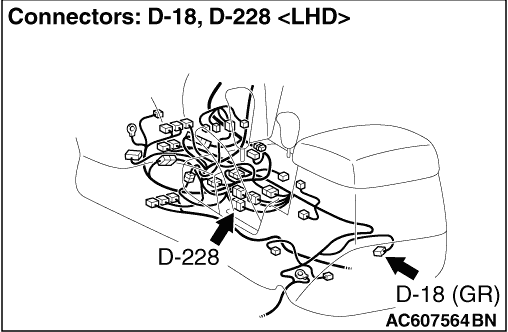
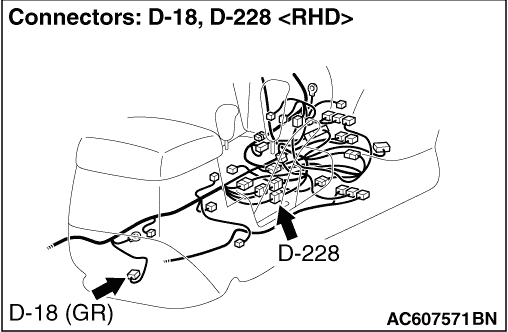
(1)Disconnect the D-18 G and yaw rate sensor connector, and remove the G and yaw rate
sensor.
|
|
|
(2)Connect the D-18 G and yaw rate sensor connector to the G and yaw rate sensor.
|
|
|
(3)Turn the ignition switch to the "ON" position.
|
|
|
(4)Check that the data list output changes within the following range when the G and
yaw rate sensor is slanted.
- Item 19: G sensor output (Front and rear)
OK: Indication varies between -14.7 and 14.7 m/s2
- Item 20: G sensor output (Left and right)
OK: Indication varies between -14.7 and 14.7 m/s2
OK: Indication varies between -50 and 50 deg/s
- Item 22: G sensor output 1
OK: Indication varies between -14.7 and 14.7 m/s2
- Item 23: G sensor output 2
OK: Indication varies between -14.7 and 14.7 m/s2
|
|
|
Q.
Is the check result normal?
|
|
|
Go to Step 9.
|
|
|
|
|
|
Go to Step 4.
|
|
|
|
|
|
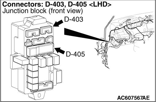
STEP 4. Check D-18 G and yaw rate sensor connector, D-228 intermediate
connector, D-403 junction block connector and D-405 junction block connector for loose, corroded
or damaged terminals, or terminals pushed back in the connector.
|
|
|
Q.
Is the check result normal?
|
|
|
Go to Step 5.
|
|
|
|
|
|
Repair or replace the damaged component(s). Then go to Step 10.
|
|
|
|
|
|
STEP 5. Check fuse No. 2.
|
|
|
Check for short to earth in the wiring harness.
|
|
|
Q.
Is the check result normal?
|
|
|
Go to Step 6.
|
|
|
|
|
|
Replace fuse No. 2. Then go to Step 10.
|
|
|
|
|
|
STEP 6. Check the power supply circuit at D-18 G and yaw rate sensor
connector.
|
|
|
(1)Disconnect D-18 G and yaw rate sensor connector, and measure at the harness side.
|
|
|
(2)Turn the ignition switch to the "ON" position.
|
|
|
(3)Measure voltage between terminal No.1 and earth.
OK: System voltage
|
|
|
Q.
Is the check result normal?
|
|
|
Go to Step 8.
|
|
|
|
|
|
Go to Step 7.
|
|
|
|
|
|
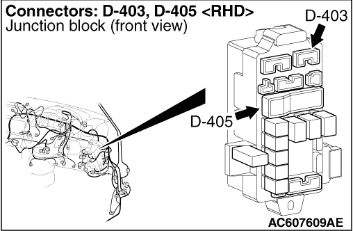
STEP 7. Check the D-403 junction block connector.
|
|
|
(1)Do not disconnect D-403 junction block connector, and measure at the junction block
side.
|
|
|
(2)Turn the ignition switch to the "ON" position.
|
|
|
(3)Measure voltage between terminal No.6 and earth.
OK: System voltage
|
|
|
Q.
Is the check result normal?
|
|
|
Repair the wiring harness between the D-405 junction block connector and the D-18
G and yaw rate sensor connector. Then go to Step 10.
|
|
|
|
|
|
Repair the wiring harness between the D-403 junction block connector and the ignition
switch (IG1). Then go to Step 10.
|
|
|
|
|
|
STEP 8. Check the earth circuit at D-18 G and yaw rate sensor connector.
|
|
|
(1)Disconnect D-18 G and yaw rate sensor connector, and measure at the harness side.
|
|
|
(2)Measure the resistance between terminal No.4 and earth.
OK: Continuity exists (2 Ω
or less)
|
|
|
Q.
Is the check result normal?
|
|
|
Go to Step 9.
|
|
|
|
|
|
Repair the wiring harness between D-18 G and yaw rate sensor connector and earth.
Then go to Step 10.
|
|
|
|
|
|
STEP 9. Check whether the diagnosis code is reset.
|
|
|
(1)Turn the ignition switch to the "ON" position.
|
|
|
(2)Erase the diagnosis code.
|
|
|
(3)Turn the ignition switch to the "LOCK" (OFF) position.
|
|
|
(4)Turn the ignition switch to the "ON" position. (Start the engine.)
|
|
|
(5)Check if the diagnosis code is set.
|
|
|
(6)Turn the ignition switch to the "LOCK" (OFF) position.
|
|
|
Q.
Is code No.63, 64, 65, 71, 72, 73, 76 or 77 set?
|
|
|
Replace the G and yaw rate sensor. Then go to Step 10.
|
|
|
|
|
|
It can be assumed that this malfunction is intermittent. Refer to GROUP 00, How
to Use Troubleshooting/Inspection Service Points -
How to Cope with Intermittent
Malfunction .
|
|
|
|
|
|
STEP 10. Check whether the diagnosis code is reset.
|
|
|
(1)Turn the ignition switch to the "ON" position.
|
|
|
(2)Erase the diagnosis code.
|
|
|
(3)Turn the ignition switch to the "LOCK" (OFF) position.
|
|
|
(4)Turn the ignition switch to the "ON" position. (Start the engine.)
|
|
|
(5)Check if the diagnosis code is set.
|
|
|
(6)Turn the ignition switch to the "LOCK" (OFF) position.
|
|
|
Q.
Is code No.63, 64, 65, 71, 72, 73, 76 or 77 set?
|
|
|
Repeat the troubleshooting from Step 1.
|
|
|
|
|
|
The procedure is complete.
|
|
|
|