REMOVAL AND INSTALLATION


warning
  • For vehicles with SRS, before removing the steering wheel and driver’s air bag module assembly, refer to GROUP 52B - Service Precautions () and Driver’s Air Bag Module(s) and Clock Spring ().
  • For vehicles with SRS, when removing and installing the steering wheel, do not let it bump against the driver’s air bag module.
caution When the steering column shaft assembly is adjusted or replaced, the calibration of steering wheel sensor must be performed (Refer to GROUP 35C - On-vehicle Service - Steering Wheel Sensor Initialisation ).
Post-installation Operation
  • Checking Steering Wheel Position with Wheels Straight Ahead


Removal steps
<<A>>

1.
Cover

>>B<<
2.
Horn connector connection
<<B>>
>>B<<

3.
Driver’s air bag module connector connection
<<C>>

4.
Driver’s air bag module


5.
Steering wheel upper cover (RH)


6.
Cruise control switch connector connection <Vehicles with cruise control switch>


7.
Cruise control switch <Vehicles with cruise control switch>


8.
Steering wheel upper cover (LH)


9.
Steering wheel audio remote control switch connector connection <Vehicles with steering wheel audio remote control switch>


10.
Steering wheel audio remote control switch <Vehicles with steering wheel audio remote control switch>


11.
Steering wheel voice control switch <Vehicles with steering wheel voice control switch>


12.
Flange nut
<<D>>
>>A<<
13.
Steering wheel assembly

REMOVAL SERVICE POINTS


<<A>> COVER REMOVAL


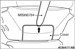
Insert special tool ornament remover (MB990784) at the indicated position to remove the cover.
note The special tool can be inserted through the notch behind the area shown.

<<B>> DRIVER’S AIR BAG MODULE CONNECTOR CONNECTION REMOVAL


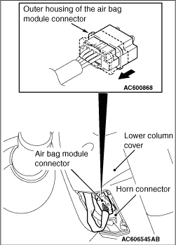
Disconnect the clock spring connector while compressing its locking button and sliding it to the direction of an arrow.

<<C>> DRIVER’S AIR BAG MODULE REMOVAL


warning
  • Never use an electric tester to diagnose the air bag module circuit. Never attempt to disassemble the air bag module.
  • The removed driver’s air bag module should be stored in a clean, dry place with the deployment surface facing up.

<<D>> STEERING WHEEL ASSEMBLY REMOVAL


caution Make sure that use the special tool to remove the steering wheel. Otherwise the steering column shaft assembly shock absorbing mechanism will be damaged.
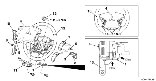
1.Position the steering wheel in the straight-ahead position.

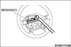
2.Use special tool steering wheel puller (MB990803) to remove the steering wheel.

INSTALLATION SERVICE POINTS


>>A<< STEERING WHEEL ASSEMBLY INSTALLATION


1.
caution When installing the steering wheel assembly and air bag module, do not trap the clock spring harness.
After centring the clock spring (Refer to 52B - Air bag module clock spring), install the steering wheel assembly.
2.After the installation, check that there is no abnormality when the steering wheel is fully turned to left and right.

>>B<< DRIVER’S AIR BAG MODULE CONNECTOR CONNECTION/HORN CONNECTOR CONNECTION


Connect the connector securely and route the harnesses not to lie off the cover hole.