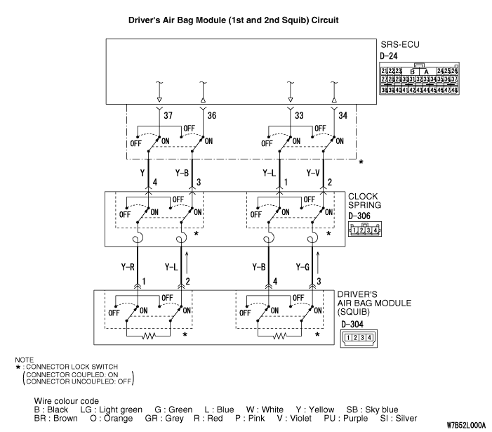
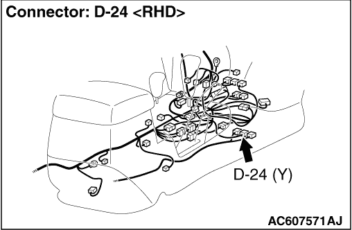
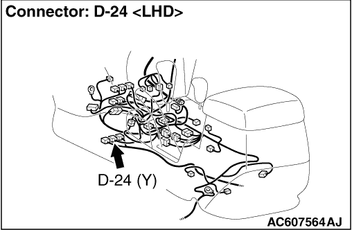
|
|
Use the M.U.T.-III to diagnose the CAN bus lines.
|
|
|
Q.
Is the check result normal?
|
|
|
 Repair the CAN bus line (Refer to GROUP 54D, Diagnosis Repair the CAN bus line (Refer to GROUP 54D, Diagnosis  ). ).
|
|
|
|
|
|
Check again if the diagnosis code is set.
|
|
|
(1)Erase the diagnosis code.
|
|
|
(2)Ignition: "LOCK" (OFF) position to "ON"
|
|
|
(3)On completion, check that the diagnosis code is not reset.
|
|
|
Q.
Is the diagnosis code set?
|
|
|
There is an intermittent malfunction such as poor engaged connector(s) or open
circuit (Refer to GROUP 00, How to Cope with Intermittent Malfunction ).
|
|
|
|
|
|
(1)Turn the ignition switch to the "ON" position.
|
|
|
(2)Check if the diagnosis code is set.
|
|
|
(3)Turn the ignition switch to the "LOOK" (OFF) position.
|
|
|
Q.
Is diagnosis code B1519 set?
|
|
|
(1)Disconnect the negative battery terminal.
|
|
|
(2)Disconnect connector D-24, and then reconnect it.
|
|
|
(3)Connect the negative battery terminal.
|
|
|
(4)Erase the diagnosis code from memory, and check the diagnosis code.
|
|
|
Q.
Is diagnosis code B1400 <1st squib> or B1480 <2nd squib> set?
|
|
|
The procedure is complete. It is assumed that diagnosis code B1400 <1st
squib> or B1480 <2nd squib> set because connector D-24 was engaged
improperly.
|
|
|
|
|
|
(1)Disconnect the negative battery terminal.
|

|
(2)Disconnect connectors D-24, D-306 and D-304, and then reconnect them. Disconnect D-304
driver’s air bag module connector while sliding its outer housing toward the arrow direction
in the illustration.
(3)Connect the negative battery terminal.
(4)Erase the diagnosis code from memory, and check the diagnosis code.
Q.
Is diagnosis code B1400 <1st squib> or B1480 <2nd squib> set?
 Go to Step 6. Go to Step 6.
The procedure is complete. It is assumed that diagnosis code B1400 <1st
squib> or B1480 <2nd squib> set because connector D-24, D-306 or
D-304 was engaged improperly.
|
|
|
(1)Disconnect the negative battery terminal.
|
|
(2)Slide the outer housing of the driver’s air bag module connector D-304 in the
arrow direction shown, and disconnect the connector.
|

|
(3)Connect special tool dummy resistor (MB991865) to special tool resistor harness (MB991866).
(4)
| caution |
Do not insert a test probe into the
terminal from its front side directly as the connector contact pressure may be weakened.
|
Insert special tool MB991866 into clock spring side of driver’s air bag module
connector D-304 (terminal No.1 and 2 <1st squib> or No.3 and 4 <2nd
squib>) by backprobing.
(5)Connect the negative battery terminal.
(6)
| caution |
Always diagnosis code B1481 is set when checking diagnosis
code B1400. This is because the second side terminal is isolated when checking it, diagnosis
code B1481 is set but this is not a fault. In addition, always diagnosis code B1401 is set when
checking diagnosis code B1480 because the first side terminal is isolated.
|
Erase the diagnosis code from memory, and check the diagnosis code.
Q.
Is the checked diagnosis code set?
Go to Step 7.
Replace the driver’s air bag module (Refer to ). Then
go to Step 10.
|
|
|
(1)Disconnect the negative battery terminal.
|
|
|
(2)Disconnect the clock spring connector D-306.
|

|
(3)Connect special tool dummy resistor (MB991865) to special tool resistor harness (MB991866).
(4)
| caution |
Do not insert a test probe into the
terminal from its front side directly, as the connector contact pressure may be weakened.
|
Insert special tool MB991866 into clock spring harness side connector D-306 (terminal
No.3 and 4 <1st squib> or No.1 and 2 <2nd squib>) by backprobing.
(5)Connect the negative battery terminal.
(6)
| caution |
Always diagnosis code B1481 is set when checking diagnosis
code B1400. This is because the second side terminal is isolated when checking it, diagnosis
code B1481 is set but this is not a fault. In addition, always diagnosis code B1401 is set when
checking diagnosis code B1480 because the first side terminal is isolated.
|
Erase the diagnosis code from memory, and check the diagnosis code.
Q.
Is the checked diagnosis code set?
Go to Step 8.
Replace the clock spring (Refer to ). Then go
to Step 10.
|
|
|
(1)Disconnect the negative battery terminal.
|
|
|
(2)Disconnect SRS-ECU connector D-24.
|
|
|
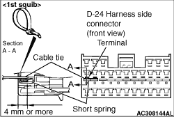
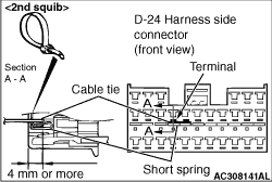
(3)
| danger |
To release SRS-ECU connector short spring in the following
operations, disconnect this clock spring connector, and keep the squib circuit shorted.
|
Disconnect clock spring connector D-306.
|
|
(4)
| caution |
Insert an insulator such as a cable tie to a depth of 4 mm or more, otherwise the short
spring will not be released.
|
Insert a cable tie [3 mm wide, 0.5 mm thick] between terminals 36 and
37 <1st squib> or 33 and 34 <2nd squib> and the short spring
to release the short spring.
(5)
| caution |
Do not insert a test probe into the terminal from
its front side directly as the connector contact pressure may be weakened.
|
Check for continuity between D-24 harness side connector terminals 36 and 37 <1st
squib> or 33 and 34 <2nd squib>.
OK: Open circuit
Q.
Is the check result normal?
Erase the diagnosis code from memory, and check the diagnosis code. If diagnosis
code B1400 <1st squib> or B1481 <2nd squib> set, replace the
SRS-ECU (Refer to ). Then go to Step 10.
Go to Step 9.
|
|
|
Q.
Are harness wires between SRS-ECU connector D-24 (terminal No.36 and 37 <1st
squib> or No.33 and 34 <2nd squib>) and clock spring connector D-306
(terminal No.3 and 4 <1st squib> or No.1 and 2 <2nd squib>)
in good condition?
|
|
|
Repair the harness wires between SRS-ECU connector D-24 and clock spring connector
D-306. Then go to Step 10.
|
|
|
|
|
|
Q.
Is diagnosis code B1400 <1st squib> or B1480 <2nd squib> set?
|
|
|
The procedure is complete.
|
|
|
|