|
|
Use the M.U.T.-III to diagnose the CAN bus lines.
|
|
|
Q.
Is the check result normal?
|
|
|
 Repair the CAN bus line (Refer to GROUP 54D, Diagnosis Repair the CAN bus line (Refer to GROUP 54D, Diagnosis  ). ).
|
|
|
|
|
|
Check again if the diagnosis code is set.
|
|
|
(1)Erase the diagnosis code.
|
|
|
(2)Ignition: "LOCK" (OFF) position to "ON"
|
|
|
(3)On completion, check that the diagnosis code is not reset.
|
|
|
Q.
Is the diagnosis code set?
|
|
|
There is an intermittent malfunction such as poor engaged connector(s) or open
circuit (Refer to GROUP 00, How to Cope with Intermittent Malfunction ).
|
|
|
|
|
|
Q.
Is the fuse burned out?
|
|
|
(1)Disconnect the negative battery terminal.
|
|
|
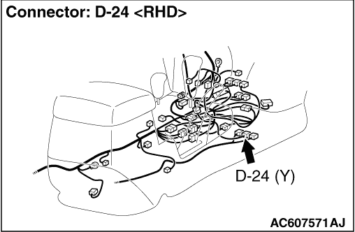
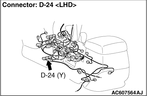
(2)Disconnect SRS-ECU connector D-24.
|
|
|
(3)Connect the negative battery terminal.
|
|
|
(4)Turn the ignition switch to the "ON" position.
|
|
|
(5)
| caution |
Do not insert a test probe into the terminal from
its front side directly as the connector contact pressure may be weakened.
|
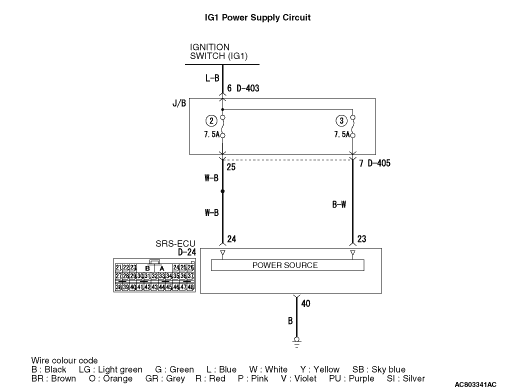
Voltage measurement between D-24 harness side connector terminal 24 <B1476>,
23 <B1477> and body earth.
OK: 9 V or more.
|
|
|
Q.
Is the check result normal?
|
|
|
Q.
Is the check result normal?
|
|
|
 Check the harness wires for open circuit between D-24 SRS-ECU connector terminal
No.24 <B1476>, 23 <B1477> and ignition switch (IG1), and repair
if necessary. Check the harness wires for open circuit between D-24 SRS-ECU connector terminal
No.24 <B1476>, 23 <B1477> and ignition switch (IG1), and repair
if necessary.
|
|
|
|
|
|
(2)Turn the ignition switch to the "ON" position, wait for at least one minute and
then turn the ignition switch to the "LOCK" (OFF) position.
|
|
|
Q.
Is the fuse in good condition?
|
|
|
(1)Disconnect SRS-ECU connector D-24.
|
|
|
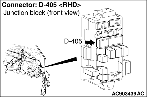
(2)Disconnect junction block connector D-405, and measure at the wiring harness side.
|
|
|
(3)
| caution |
Do not insert a test probe into the terminal from
its front side directly as the connector contact pressure may be weakened.
|
Resistance measurement between terminal No.25 <B1476>, 7 <B1477> and
body earth.
OK: Open circuit
|
|
|
Q.
Is the check result normal?
|
|
|
Check the other circuit which flows through fuse No.2 and No.3.
|
|
|
|
|
|
Repair the wiring harness between D-405 junction block connector terminal No.25 <B1476>,
7 <B1477> and D-24 SRS-ECU connector terminal No.24 <B1476>,
23 <B1477>, and replace the fuse.
|
|
|
|
|
|
Q.
Is diagnosis code B1476 or B1477 set?
|
|
|
Replace the SRS-ECU (Refer to ).
|
|
|
|
|
|
An intermittent malfunction is suspected (Refer to GROUP 00, How to Cope with
Intermittent Malfunction ).
|
|
|
|