|
|
Q.
Is the fuse in good condition?
|
|
|
(2)Turn the ignition switch to the "ON" position, wait for at least one minute, and
then turn the switch OFF.
|
|
|
Q.
Is the fuse in good condition?
|
|
|
 Repair the wiring harness between the D-405 junction block connector (terminal
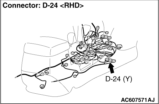
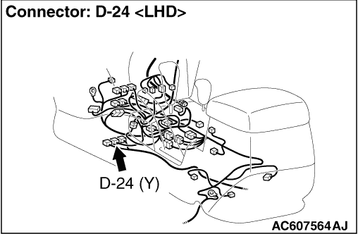
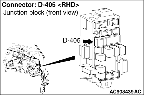
No.7 and 25) and the D-24 SRS-ECU connector terminal (No. 23 and 24), and replace the fuse. Repair the wiring harness between the D-405 junction block connector (terminal
No.7 and 25) and the D-24 SRS-ECU connector terminal (No. 23 and 24), and replace the fuse.
|
|
|
|
|
|
(1)Disconnect the negative battery terminal.
|
|
|
(2)Disconnect the connector D-24.
|
|
|
(3)
| caution |
Do not insert a test probe into the terminal from
its front side directly, as the connector contact pressure may be weakened.
|
Check for continuity between D-24 harness side connector terminals 40 and body earth.
OK: Continuity (Less than 2 Ω)
|
|
|
Q.
Is the check results normal?
|
|
|
Repair the wiring harness between SRS-ECU connector D-24 terminals 40 and the
body earth. Then go to Step 6.
|
|
|
|
|
|
(1)Disconnect the negative battery terminal.
|
|
|
(2)Disconnect SRS-ECU connector D-24.
|
|
|
(3)Connect the negative battery terminal.
|
|
|
(4)Turn the ignition switch to the "ON" position.
|
|
|
(5)
| caution |
Do not insert a test probe into the terminal from
its front side directly as the connector contact pressure may be weakened.
|
Voltage measurement between D-24 harness side connector terminal No. 23, 24 and body earth.
OK: 9 V or more.
|
|
|
Q.
Is the check result normal?
|
|
|
Q.
Is the check result normal?
|
|
|
 Check the harness wires for open circuit between D-24 SRS-ECU connector terminal
No.23, 24 and ignition switch, and repair if necessary. Check the harness wires for open circuit between D-24 SRS-ECU connector terminal
No.23, 24 and ignition switch, and repair if necessary.
|
|
|
|
|
|
Q.
Can the SRS-ECU communicate with the M.U.T.-III?
|
|
|
It can be assumed that this malfunction is intermittent. Refer to GROUP 00, How
to Cope with Intermittent Malfunction  . .
|
|
|
|
|
|
Replace the SRS-ECU (Refer to ).
|
|
|
|