Inspection Procedure 5: The Auto Lamp Function does not Work Normally. <Using SWS Monitor>
| caution | Before replacing the ECU, ensure that the power supply circuit, the earth circuit and the communication circuit are normal. |


OPERATION
COMMENTS ON TROUBLE SYMPTOM
PROBABLE CAUSES
- Malfunction of the lighting control sensor
- Malfunction of the CAN converter-ECU
- Malfunction of the column switch
- Malfunction of the front-ECU
- Damaged harness wires and connectors
DIAGNOSIS PROCEDURE
STEP 1. Check that the headlamps operate.
Q.
Is the check result normal?


STEP 2. M.U.T.-III diagnosis code
Q.
Is the diagnosis code set?
STEP 3. M.U.T.-III other system diagnosis code
Q.
Is the diagnosis code set?
STEP 4. SWS monitor data list.
<Selected item> LIGHTING - AUTO (HEAD)
- Ignition switch: "ON"
- Column switch (lighting switch): "AUTO"
|
Q.
Is the check result normal?

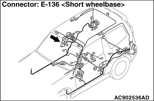
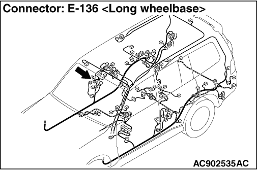
STEP 5. Connector check: E-136 Lighting control sensor connector
Q.
Is the check result normal?
STEP 6. Resistance measurement at the E-136 lighting control sensor connector
| (1)Disconnect the lighting control sensor connector, and measure at the wiring harness side. |
| (2)Measure the resistance between E-136 lighting control sensor connector terminal No.2 and body earth. OK: Continuity exists (2 Ω or less) |
Q.
Is the check result normal?
STEP 7. Check the wiring harness between E-136 lighting control sensor connector terminal No.2 and body earth.
- Check the earth wires for open circuit.
Q.
Is the check result normal?
STEP 8. Voltage measurement at the E-136 lighting control sensor connector.
| (1)Disconnect the lighting control sensor connector, and measure at the wiring harness side. |
| (2)Measure the voltage between E-136 lighting control sensor connector terminal No. 1 and body earth. OK: System voltage |
Q.
Is the check result normal?
STEP 9. Check the wiring harness between E-136 lighting control sensor connector terminal No. 1 and fusible link (1).
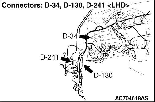
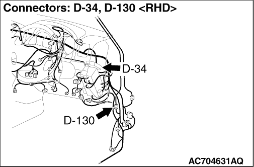
| note | Prior to the wiring harness inspection, check intermediate connector D-241, D-130 and joint connector D-34, and repair if necessary. |
- Check the power supply line for open circuit and short circuit.
Q.
Is the check result normal?
STEP 10. Connector check: D-252 CAN converter-ECU connector
Q.
Is the check result normal?
STEP 11. Voltage measurement at the E-136 lighting control sensor connector.
| (1)Disconnect the lighting control sensor connector, and measure at the wiring harness side. |
| (2)Turn the ignition switch from "LOCK" (OFF) to "ON" position. |
| (3)Measure the voltage between E-136 lighting control sensor connector terminal No. 3 and body earth. OK: System voltage |
Q.
Is the check result normal?
STEP 12. Check the wiring harness wires between D-252 CAN converter-ECU terminal No.12 and E-136 lighting control sensor connector terminal No.3.
| note | Prior to the wiring harness inspection, check intermediate connector D-130, and repair if necessary. |
- Check the communication lines for open circuit and short circuit.
Q.
Is the check result normal?
STEP 13. Check the windshield surface to which the lighting control sensor is installed.
Q.
Is the check result normal?
STEP 14. Lighting control sensor removal and installation
Q.
Is the check result normal?
STEP 15. Retest the system
Q.
Is the check result normal?
STEP 16. Temporarily replace the lighting control sensor, and check the trouble symptom.
Q.
Is the check result normal?