Code No.U1570 CAN-LIN-SWS converter (LIN bus)
| caution | Before replacing the ECU, ensure
that the power supply circuit, the earth circuit and the communication circuit are normal. |


TROUBLE JUDGMENT
COMMENTS ON TROUBLE SYMPTOM
PROBABLE CAUSES
- Malfunction of the CAN converter-ECU
- Malfunction of the lighting control sensor
- LIN bus lines shorted to power supply
- LIN bus lines shorted to earth
- Open circuit of LIN bus line
DIAGNOSIS PROCEDURE
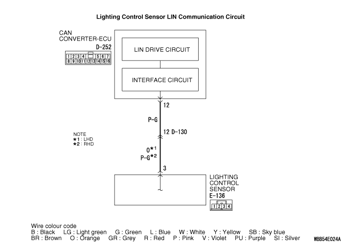
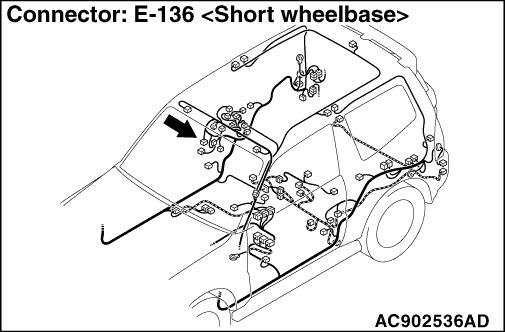
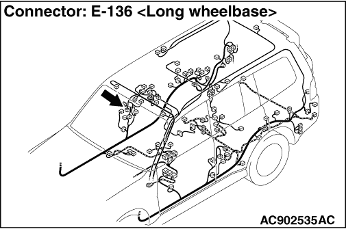
STEP 1. Connector check: D-252 CAN converter-ECU connector, E-136 lighting control sensor connector
Q.
Is the check result normal?


STEP 2. Check the wiring harness wires between D-252 CAN converter-ECU terminal No. 12 and E-136 lighting control sensor connector terminal No. 3.
- Check the communication lines for open circuit and short circuit.
Q.
Is the check result normal?
STEP 3. Measure the voltage at the LIN bus lines.
| (1)Disconnect the CAN converter-ECU connector and the lighting control sensor connector connected
to the LIN bus line. |
| (2)Turn the ignition switch from "LOCK" (OFF) to "ON" position. |
| (3)Measure the voltage between E-136 lighting control sensor connector (wiring harness
side) terminal No. 3 and earth. OK: The voltmeter needle does not swing.
|
Q.
Is the check result normal?
STEP 4. Measure the resistance at the LIN bus lines.
| (1)Disconnect the CAN converter-ECU connector and the lighting control sensor connector connected
to the LIN bus line. |
| (2)Measure the continuity between E-136 lighting control sensor connector (wiring
harness side) terminal No. 3 and earth. OK: No continuity (1 kΩ or more) |
Q.
Is the check result normal?
STEP 5. M.U.T.-III other system diagnosis code
Q.
Is the diagnosis code set?

STEP 6. Check whether the diagnosis code is reset.
| (1)Replace the lighting control sensor. |
| (2)Erase the diagnosis code. |
| (3)Turn the ignition switch from "LOCK" (OFF) position to "ON" position. |
| (4)Check if diagnosis code is set. |
Q.
Is the diagnosis code set?