Inspection Procedure 9: Malfunction of the CAN Converter-ECU power supply circuit.
| caution | Before replacing the ECU, ensure that the power supply circuit, the earth circuit and the communication circuit are normal. |


PROBABLE CAUSES
- Damaged harness wires and connectors
DIAGNOSIS PROCEDURE
STEP 1. Connector check: D-252 CAN converter-ECU connector
Q.
Is the check result normal?


STEP 2. Voltage measurement at the D-252 CAN converter-ECU connector.
| (1)Disconnect the CAN converter-ECU connector, and measure at the wiring harness side. |
| (2)Measure the voltage between D-252 CAN converter-ECU connector terminal No. 1 and body earth. OK: System voltage |
| (3)With the ignition switch turned to the "ON" position, measure the voltage between D-252 CAN converter-ECU connector terminal No. 2 and body earth. OK: System voltage |
Q.
Is the check result normal?
STEP 3. Check the wiring harness between D-252 CAN converter-ECU connector terminal No. 1 and fusible link (1), or between D-252 CAN converter-ECU connector terminal No. 2 and ignition switch (IG1).
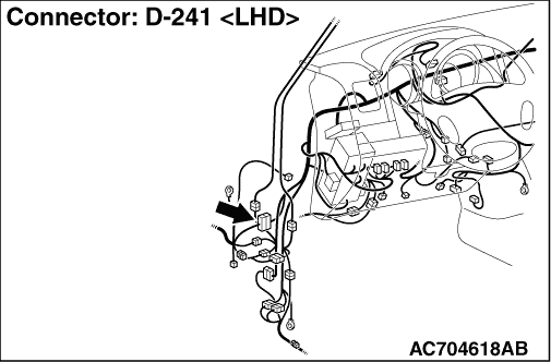
| note | Prior to the wiring harness inspection, check intermediate connector D-241 and junction block connector D-403 and D-405, and repair if necessary. |
- Check the power supply line for open circuit and short circuit.
Q.
Is the check result normal?

STEP 4. Resistance measurement at the D-252 CAN converter-ECU connector.
| (1)Disconnect the CAN converter-ECU connector, and measure at the wiring harness side. |
| (2)Continuity between D-252 CAN converter-ECU connector terminal No.16 and body earth. OK: Continuity exists (2 Ω or less) |
Q.
Is the check result normal?
STEP 5. Check the wiring harness between D-252 CAN converter-ECU connector terminal No.16 and body earth.
- Check the earth wires for open circuit.
Q.
Is the check result normal?