|
|
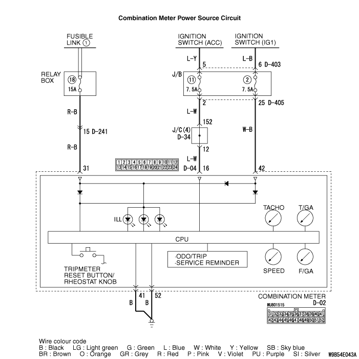
If the odometer and trip meter are not displayed or all meter needles don’t move, power supply and earth system to the combination meter, or the combination meter itself may be defective.
|
|
|
- Damaged harness wires and connectors
- Malfunction of combination meter
|
|
|
Q.
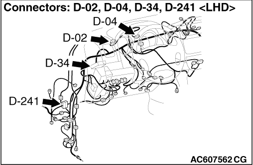
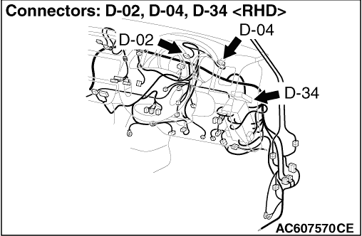
Are combination meter connectors D-02 and D-04 in good condition?
|
|
|
 Repair the defective connector. Repair the defective connector.
|
|
|
|
|
|
(1)Disconnect combination meter connector D-02, and measure at the wiring harness side.
|
|
|
(2)Turn the ignition switch to "LOCK" (OFF) position.
|
|
|
(3)Measure the voltage between terminal 31 and body earth.
OK: System voltage
|
|
|
Q.
Is the check result normal?
|
|
|
- Check the power supply line for open circuit and short circuit.
|
|
|
Q.
Is the wiring harness between combination meter connector D-02 (terminal 31) and battery (fusible link No.1) in good condition?
|
|
|
Repair the wiring harness.
|
|
|
|
|
|
(1)Disconnect combination meter connector D-04, and measure at the wiring harness side.
|
|
|
(2)Turn the ignition switch to "ACC" position.
|
|
|
(3)Measure the voltage between terminal 16 and body earth.
OK: System voltage
|
|
|
Q.
Is the check result normal?
|
|
|
- Check the power supply line for open circuit and short circuit.
|
|
|
Q.
Is the wiring harness between combination meter connector D-04 (terminal 16) and ignition switch (ACC) in good condition?
|
|
|
Repair the wiring harness.
|
|
|
|
|
|
(1)Disconnect combination meter connector D-02, and measure at the wiring harness side.
|
|
|
(2)Turn the ignition switch to "ON" position.
|
|
|
(3)Measure the voltage between terminal 42 and earth.
OK: System voltage
|
|
|
Q.
Is the check result normal?
|
|
|
- Check the power supply line for open circuit and short circuit.
|
|
|
Q.
Is the wiring harness between combination meter connector C-02 (terminal 42) and ignition switch (IG1) in good condition?
|
|
|
Repair the wiring harness.
|
|
|
|
|
|
(1)Disconnect combination meter connector D-02, and measure at the wiring harness side.
|
|
|
(2)Measure the resistance between terminal 41 and body earth.
OK: Continuity exists (2 Ω or less)
|
|
|
(3)Measure the resistance between terminal 52 and body earth.
OK: Continuity exists (2 Ω or less)
|
|
|
Q.
Is the check result normal?
|
|
|
- Check the earth wires for open circuit.
|
|
|
Q.
Are the wiring harness between combination meter connector D-02 (terminals 41 and 52) and body earth in good condition?
|
|
|
Repair the wiring harness.
|
|
|
|
|
|
Q.
Is the check result satisfactory?
|
|
|
 Intermittent Malfunction (Refer to GROUP 00 - How to Cope with Intermittent Malfunction Intermittent Malfunction (Refer to GROUP 00 - How to Cope with Intermittent Malfunction  .) .)
|
|
|
|
|
|
Replace the combination meter.
|
|
|
|