|
|
The ETACS-ECU communicates with the front-ECU through the SWS communication line. If there
is any trouble in that communication, diagnosis code No.03 will be set.
|
|
|
The front-ECU, the ETACS-ECU, connector(s), or wiring harness between the two may be defective.
|
|
|
- Malfunction of the front-ECU
- Malfunction of the ETACS-ECU
- Damaged harness wires and connectors
|
|
|
Use the M.U.T.-III to diagnose the CAN bus lines.
|
|
|
Q.
Is the check result normal?
|
|
|
 Repair the CAN bus line (Refer to GROUP 54D - Troubleshooting Repair the CAN bus line (Refer to GROUP 54D - Troubleshooting  ). ).
|
|
|
|
|
|
(1)Erase the diagnosis code.
|
|
|
(2)Ignition switch: LOCK (OFF) position to ON
|
|
|
(3)On completion, check that diagnosis code No.03 is not reset.
|
|
|
Q.
Is diagnosis code No.03 set?
|
|
|
The trouble can be an intermittent malfunction (Refer to GROUP 00 - How
to use troubleshooting/Inspection Service Points ).
|
|
|
|
|
|
Q.
Is the check result normal?
|
|
|
Repair the defective connector.
|
|
|
|
|
|
(1)Remove the front-ECU, and measure at the relay box side.
|
|
|
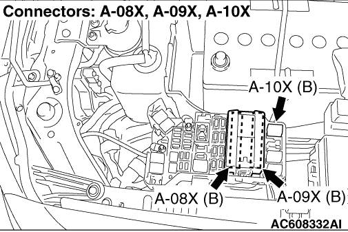
(2)Voltage between A-08X front-ECU connector terminal No.7 and body earth
OK: System voltage
|
|
|
Q.
Is the check result normal?
|
|
|
- Check the power supply line for open circuit.
|
|
|
Q.
Is the check result normal?
|
|
|
 The trouble can be an intermittent malfunction (Refer to GROUP 00 - How
to use troubleshooting/Inspection Service Points ). The trouble can be an intermittent malfunction (Refer to GROUP 00 - How
to use troubleshooting/Inspection Service Points ).
|
|
|
|
|
|
Repair the wiring harness.
|
|
|
|
|
|
Q.
Is the check result normal?
|
|
|
Repair the defective connector.
|
|
|
|
|
|
(1)Remove the front-ECU, and measure at the relay box side.
|
|
|
(2)Turn the ignition switch to the ON position.
|
|
|
(3)Voltage between A-09X front-ECU connector terminal No.30 and body earth
OK: System voltage
|
|
|
Q.
Is the check result normal?
|
|
|
- Check the power supply line for open circuit.
|
|
|
Q.
Is the check result normal?
|
|
|
Refer to GROUP 54A - Ignition switch .
|
|
|
|
|
|
Repair the wiring harness.
|
|
|
|
|
|
(1)Remove the front-ECU, and measure at the relay box side.
|
|
|
(2)Resistance between A-09X front-ECU connector terminal No.31 and body earth
OK: Continuity exists (2 Ω or less)
|
|
|
Q.
Is the check result normal?
|
|
|
- Check the earth wires for open circuit.
|
|
|
Q.
Is the check result normal?
|
|
|
The trouble can be an intermittent malfunction (Refer to GROUP 00 - How
to use troubleshooting/Inspection Service Points ).
|
|
|
|
|
|
Repair the wiring harness.
|
|
|
|
|
|
Q.
Is the check result normal?
|
|
|
Repair the defective connector.
|
|
|
|
|
|
- Check the communication lines for open and short circuit.
|
|
|
Q.
Is the check result normal?
|
|
|
Repair the wiring harness.
|
|
|
|
|
|
Replace the front-ECU, and then check that the diagnosis code is not reset to the ETACS-ECU.
|
|
|
(1)Replace the front-ECU.
|
|
|
(2)Erase the diagnosis code.
|
|
|
(3)Ignition switch: LOCK (OFF) position to ON
|
|
|
(4)On completion, check that diagnosis code No.03 is not reset.
|
|
|
Q.
Is diagnosis code No.03 set?
|
|
|
The procedure is complete.
|
|
|
|