|
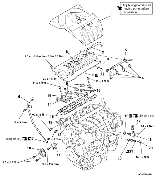
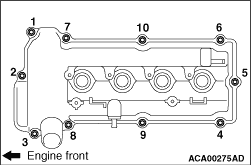
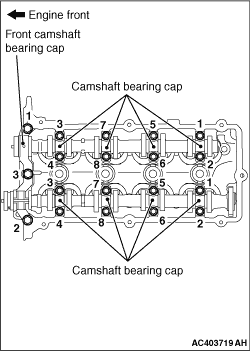
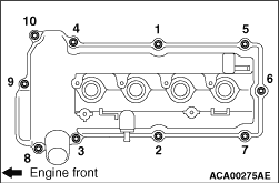
Loosen the cylinder head cover assembly mounting bolts in the order of the numbers shown
in the illustration, and remove the cylinder head cover assembly.
|
|
1.
| caution |
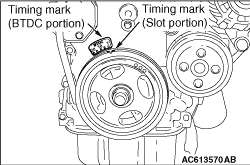
Never turn the crankshaft anti-clockwise.
|
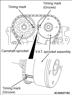
Turn the crankshaft clockwise, and align the timing mark of the crankshaft with the T
position of BTDC. Then, align the timing mark of the camshaft sprocket (2 conceive areas in front
of the camshaft sprocket) and that of the V.V.T. sprocket assembly (the groove of V.V.T. sprocket
assembly side face). Then set No.1 cylinder to the top dead centre of compression
|
|
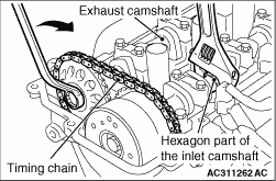
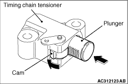
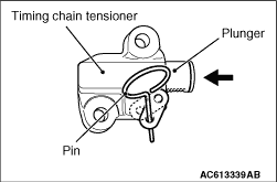
2.While holding the inlet camshaft hexagonal area with a wrench or a similar tool, slightly
turn the exhaust camshaft clockwise to tighten the timing chain at the timing chain tensioner
side and shorten the plunger of the timing chain tensioner.
|
|
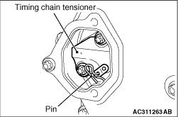
3.With the plunger of the tensioner shortened, insert a pin or a similar tool (3 mm or less
in diameter) to the hole shown in the illustration of the timing chain tensioner.
4.
| caution |
Do not turn the crankshaft after removing the timing
chain tensioner.
|
Loosen the timing chain tensioner mounting bolts, and remove the timing chain tensioner
from the timing chain case hole.
|

|
1.Fix the camshaft sprocket and the timing chain using a cable band or a similar tool.
|
|
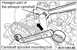
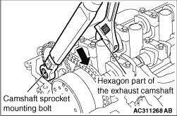
2.While holding the exhaust camshaft hexagonal area with a wrench or a similar tool, loosen
the camshaft sprocket mounting bolt.
|
|
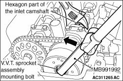
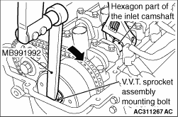
3.While holding the inlet camshaft hexagonal area using a wrench or a similar tool, use
special tool torque wrench adapter (MB991992) to loosen the V.V.T. sprocket assembly mounting
bolt.
|
|
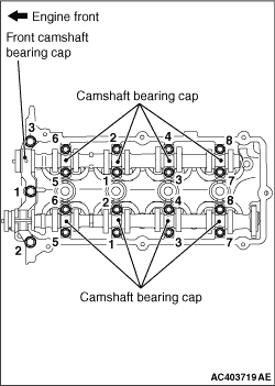
4.Loosen the front camshaft bearing cap mounting bolts, and then loosen each camshaft bearing
cap mounting bolts in the order shown. Remove the front camshaft bearing cap and each camshaft
bearing cap.
|
|
5.
| caution |
Do not turn the crankshaft after removing the camshaft sprocket
assembly with the timing chain.
|
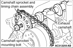
Slightly raise the exhaust camshaft with the camshaft sprocket and timing chain assembly
from the cylinder head, remove the camshaft sprocket mounting bolt, and disconnect the camshaft
sprocket and timing chain assembly from the exhaust camshaft.
6.In the same way as Step 5, disconnect the V.V.T. sprocket assembly and timing chain
assembly from the inlet camshaft.
7.
| caution |
After disconnecting the camshaft sprocket and the V.V.T. sprocket
assembly (with the timing chain for each) from the camshaft, do not dislocate the camshaft sprocket,
the V.V.T. sprocket assembly, and the timing chain.
|
After removal, place the camshaft sprocket and timing chain assembly, and the V.V.T. sprocket
assembly and timing chain assembly on the timing chain case assembly.
|
|
|
1.Cover the oil groove of the oil feeder control valve with a cardboard.
|
|
|
2.
| caution |
When installing the O-ring to the oil feeder control
valve, take care not to damage the O-ring.
|
Apply the engine oil to the O-ring and install it to the oil feeder control valve.
|
|
|
3.
| caution |
When installing the oil feeder control valve to the cylinder head,
take care not to damage the O-ring.
|
Apply the engine oil to the O-ring and install the oil feeder control valve to the cylinder
head.
|
|
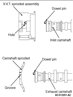
1.First, lift the V.V.T. sprocket assembly side of the camshaft sprocket, V.V.T. sprocket
assembly and the timing chain assembly. Then align the dowel pin of the inlet camshaft with the
V.V.T. sprocket assembly hole, and assemble the inlet camshaft and the V.V.T. sprocket assembly.
Temporarily tighten the mounting bolt.
2.Next, lift the camshaft sprocket side of the camshaft sprocket, V.V.T. sprocket assembly
and the timing chain assembly. Then align the dowel pin of the exhaust camshaft with the camshaft
sprocket groove, and assemble the exhaust camshaft and the camshaft sprocket. Temporarily tighten
the mounting bolt.
3.Place the inlet camshaft and exhaust camshaft on the installing location of the cylinder
head.
|
|
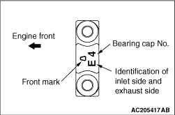
4.The No.2 to No.5 bearing caps are equally shaped for both the inlet and exhaust camshafts.
Be sure to correctly install them by referring to the identification marks.
Identification mark (stamped on the front and No.2
to No.5 bearing caps)
|
|
5.Tighten each camshaft bearing cap mounting bolts to the specified torque in the order
shown, and then tighten the front camshaft bearing cap mounting bolts as well.
Tightening torque:
11 ± 1 N·m (Camshaft bearing cap
mounting bolts)
20 ± 1 N·m (Front camshaft bearing cap mounting bolts)
|
|
6.While holding the inlet camshaft hexagonal area using a wrench or a similar tool, use
special tool torque wrench adapter (MB991992) to tighten the V.V.T. sprocket assembly mounting
bolt to the specified torque. Since the V.V.T. sprocket assembly mounting bolt is tightened
by special tool (MB991992), calculate the tightening torque by the following formula.
Tightening torque: (65 ± 5) × {L ÷ (L + 150)} N·m
65 ± 5: Tightening torque of the V.V.T. sprocket assembly
mounting bolt (unit: N·m)
L: Distance between the centre of a torque wrench drive and of its handle (unit:
mm)
150: Length of special tool (unit: mm)
|
|
7.While holding the exhaust camshaft hexagonal area using a wrench or similar tool, tighten
the camshaft sprocket mounting bolt to the specified torque.
Tightening torque: 92 ± 13 N·m
|
|
1.Install the timing chain guide, the tensioner lever assembly, and the timing chain tensioner.
| note |
When the plunger of the timing chain tensioner is stretched, remove the pin or the similar
tool. While pressing the cam in the lower area of the timing chain tensioner, press and shorten
the plunger to keep the status with the pin or the similar tool.
|
2.Tighten the timing chain tensioner mounting bolts to the specified torque.
Tightening torque: 9.5 ± 2.5 N·m
3.After installing the timing chain tensioner, confirm that the timing marks of each
sprocket are aligned with the TDC of No.1 cylinder, and the marked link plate (blue-coloured
area) of the timing chain is aligned with the specified position of each sprocket. Then pull
out the pin or a similar tool of the timing chain tensioner, and apply tension to the timing
chain.
|
|
|
1.Remove the sealant from the installation face of the timing chain tensioner cover
and the timing chain case assembly, and degrease the surface where the sealant is applied.
|
|
2.
| caution |
After the installation, until a sufficient period of time (one hour or
more) elapses, do not apply the engine oil or water to the sealant application area or start
the engine.
|
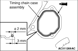
Apply a bead of the specified sealant to the mating surface of the timing chain case assembly.
Then, install the timing chain tensioner cover to the timing chain case assembly.
Specified sealant: ThreeBond 1217G or equivalent
| note |
Install the timing chain tensioner cover immediately after the application of sealant.
|
|
|
|
1.Remove the sealant from the cylinder head cover assembly and the matching area of
the cylinder head assembly and the timing chain case assembly, and degrease the surface where
the sealant is applied.
|
|
2.
| caution |
After the installation, until a sufficient period of time (one hour or
more) elapses, do not apply the engine oil or water to the sealant application area or start
the engine.
|
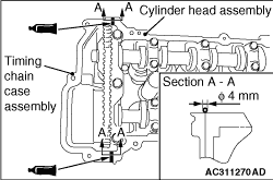
Apply specified sealant to the matching area of the cylinder head assembly and the timing
chain case assembly as shown, and install the cylinder head cover assembly to the cylinder head
assembly.
Specified sealant: ThreeBond 1217G or equivalent
| note |
Install the cylinder head cover assembly immediately after the application of sealant.
|
|
|
3.Tighten the cylinder head cover assembly mounting bolts to the specified torque in the
order of the numbers shown in the illustration.
Tightening torque: 3.0 ± 1.0 N·m
4.Tighten again the cylinder head cover assembly mounting bolts to the specified torque
in the order of number shown in the figure.
Tightening torque: 5.5 ± 0.5 N·m
|