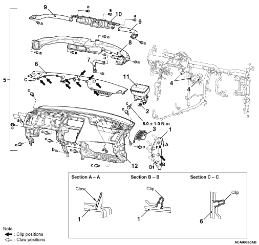
REMOVAL AND INSTALLATION


Name
Symbol
Size (D × L) mm
Colour
Shape
Tapping screw
a
5 × 14
-


b
5 × 16
-


Bolt with washer
c
6 × 16
-


caution
  • Before removing the front passenger’s air bag module, refer to GROUP 52B - Service Precautions (refer to ) and Driver’s Air bag Module, Clock Spring (refer to ) and Passenger’s (front) Air bag Module (refer to ).
  • Do not subject the SRS-ECU to any shocks when removing or installing the instrument panel.
Pre-removal and Post-installation Operation
  • Removal and Installation of Front Pillar Trim (Refer to ).
  • Removal and Installation of Instrument Panel Under Cover (Refer to ).
  • Removal and Installation of Glove Box Upper Cover (Refer to ).
  • Removal and Installation of Instrument panel cover lower (Refer to ).
  • Removal and Installation of Knee Air Bag Module (Refer to GROUP 52B - Knee Air Bag Module ).
  • Removal and Installation of Multivision Display Assembly/CAV Box Unit Assembly (Refer to GROUP 54A - Mitsubishi Multi Communication System (MMCS) ).
  • Removal and Installation of Combination Meter Assembly (Refer to GROUP 54A - Combination Meter ).


Removal steps


1.
Instrument panel side cover


·.
Glove box side cover (Refer to .)


2.
Passenger’s (front) air bag module connector connection (Refer to GROUP 52B - Passenger’s (front) air bag module .)


·.
Interior temperature sensor (Refer to GROUP 55 - Interior temperature sensor .)


3.
Instrument trim panel side air outlet


4.
Instrument panel harness clamp


5.
Instrument trim assembly


6.
Instrument trim panel


7.
Cooler duct


8.
Ventilation air distribution duct


9.
Defroster side duct


10.
Defroster nozzle


11.
Passenger’s (front) air bag module


12.
Instrument panel