BRAKE PEDAL CHECK AND ADJUSTMENT
|
BRAKE PEDAL HEIGHT CHECK AND ADJUSTMENT |
| 1.Turn up the floor carpet under the brake pedal. |
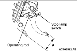 |
2.Measure the brake pedal height. Standard value (A):
143.4 to 146.4 mm <RHD> |
  |
3.When the brake pedal height is not within the standard value, adjust the brake pedal
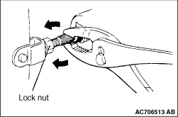
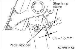
in the following procedure. (1) Disconnect the stop lamp switch connector. (2) Loosen the stop lamp switch by turning it anti-clockwise by approximately 1/4 turn. (3) Loosen the lock nut of operating rod, then turn the serrated section of operating rod using the pliers to adjust the brake pedal height to the standard value. (4) Press in the stop lamp switch until the thread section of stop lamp switch comes in contact with the pedal stopper. Then, secure the stop lamp switch by turning it clockwise by approximately 1/4 turn. While doing this, pull and hold the brake pedal by hand. (5) Check that the clearance between the stop lamp switch and the pedal stopper is as shown in the figure. (6)
4.Perform the key interlock mechanism check (refer to GROUP 22A - On-vehicle Service, Key Interlock Mechanism Check  ) and the shift
lock mechanism check (refer to GROUP 22A - On-vehicle Service, Shift Lock Mechanism
Check ). ) and the shift
lock mechanism check (refer to GROUP 22A - On-vehicle Service, Shift Lock Mechanism
Check ).5.Recover the floor carpet under the brake pedal. 6.After adjusting the brake pedal height, initialize the brake pedal stroke sensor installed to the brake pedal assembly in the following procedure. (1) Disconnect the auxiliary battery (-) terminal. (Refer to GROUP 54A - Auxiliary battery )(2) Disconnect the auxiliary battery (-) terminal and wait for 1 minute. (3) After 1 minute, connect the auxiliary battery (-) terminal. (Refer to GROUP 54A - Auxiliary battery ) |
BRAKE PEDAL PLAY CHECK AND ADJUSTMENT |
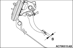 |
1.Set the electric motor switch to the LOCK (OFF) position, and depress the brake pedal
two to three times to relief the brake booster vacuum pressure. Then, press the brake pedal
with your fingers to check that the pedal stroke until the pedal effort becomes heavy (play)
is within the standard value. Standard value (B): 3 to 8 mm 2.When the brake pedal play is not within the standard value, check the brake pedal-to-clevis pin looseness, clevis pin-to-booster operating rod looseness, brake pedal height, and stop lamp switch position, and adjust or replace as necessary. 3.After adjusting the brake pedal play, initialize the brake pedal stroke sensor installed to the brake pedal assembly in the following procedure. (1) Disconnect the auxiliary battery (-) terminal. (Refer to GROUP 54A - Auxiliary battery )(2) Disconnect the auxiliary battery (-) terminal and wait for 1 minute. (3) After 1 minute, connect the auxiliary battery (-) terminal. (Refer to GROUP 54A - Auxiliary battery ) |
BRAKE PEDAL-TO-FLOOR CLEARANCE CHECK AND ADJUSTMENT |
| 1.Turn up the floor carpet under the brake pedal. |
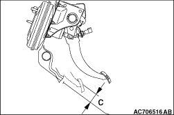 |
2.Set the electric motor switch to the ON position, then depress the brake pedal with approximately
500 N, and measure the clearance between the brake pedal and the floor. Standard value (C):
60 mm or more <RHD> 4.Recover the floor carpet under the brake pedal. |