|
|
The G and yaw rate sensor output signal is sent to ASC-ECU via the CAN bus lines.
|
|
|
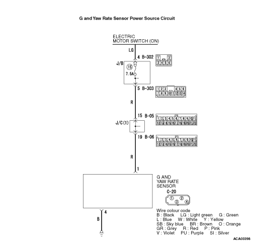
The G and yaw rate sensor monitors the power supply voltage supplied from the electric
motor switch "ON", and if the sensor determines that the voltage value is abnormality, it sets
this code.
|
|
|
- Damaged harness wires and connectors
- Charging circuit failure
- Malfunction of the G and yaw rate sensor
|
|
|
Use the M.U.T.-III to diagnose the CAN bus lines.
|
|
|
Q.
Is the check result normal?
|
|
|
 Repair the CAN bus lines (Refer to GROUP 54C - CAN Bus Diagnostics Table Repair the CAN bus lines (Refer to GROUP 54C - CAN Bus Diagnostics Table  ).
On completion, go to Step 2. ).
On completion, go to Step 2.
|
|
|
|
|
|
Q.
Is the diagnosis code No.C1864 set?
|
|
|
This diagnosis is complete.
|
|
|
|
|
|
Q.
Is the battery in good condition?
|
|
|
Replace the auxiliary battery. Then go to Step 4.
|
|
|
|
|
|
Check if diagnosis code is set to the OBC.
|
|
|
Q.
Is the diagnosis code set?
|
|
|
 Troubleshooting the OBC (Refer to GROUP 54D - OBC/Diagnosis
Code Chart ). Then go to Step 5. Troubleshooting the OBC (Refer to GROUP 54D - OBC/Diagnosis
Code Chart ). Then go to Step 5.
|
|
|
|
|
|
Q.
Is the check result normal?
|
|
|
Repair the damaged connector.
|
|
|
|
|
|
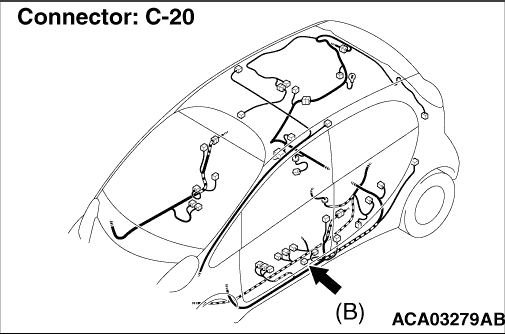
(1)Disconnect the C-20 G and yaw rate sensor connector, and measure at the harness
side connector.
|
|
|
(2)Measure the voltage at the C-20 G and yaw rate sensor connector terminal No.1 and
body earth.
OK: Battery voltage
|
|
|
Q.
Is the check result normal?
|
|
|
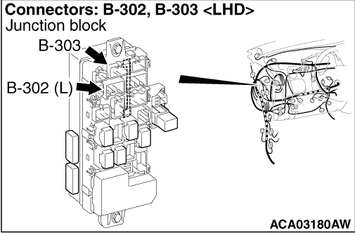
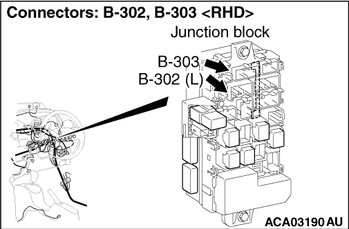
(1)Disconnect the C-20 G and yaw rate sensor connector and the B-303 junction block
connector, and measure at the harness side connector.
|
|
|
(2)Measure the resistance at the C-20 G and yaw rate sensor connector terminal No.1
and B-303 junction block connector terminal No.5.
OK: Continuity exists (2 Ω or less)
|
|
|
Q.
Is the check result normal?
|
|
|
Repair the wiring harness.
|
|
|
|
|
|
(1)Disconnect the C-20 G and yaw rate sensor connector, and measure at the harness
side connector.
|
|
|
(2)Measure the resistance at the C-20 G and yaw rate sensor connector terminal No.4
and body earth.
OK: Continuity exists (2 Ω or less)
|
|
|
Q.
Is the check result normal?
|
|
|
Repair the wiring harness.
|
|
|
|
|
|
(1)Erase the diagnosis code.
|
|
|
(2)Turn the electric motor switch from "LOCK" (OFF) position to "ON" position.
|
|
|
Q.
Is the diagnosis code No.C1864 set?
|
|
|
Replace the G and yaw rate sensor (Refer to ).
Then go to Step 10.
|
|
|
|
|
|
Intermittent malfunction (Refer to GROUP 00 - How to Use Troubleshooting/How
to Cope with Intermittent Malfunctions ).
|
|
|
|
|
|
(1)Erase the diagnosis code.
|
|
|
(2)Turn the electric motor switch from "LOCK" (OFF) position to "ON" position.
|
|
|
Q.
Is the diagnosis code No.C1864 set?
|
|
|
This diagnosis is complete.
|
|
|
|