REMOVAL AND INSTALLATION


danger
  • When servicing the high voltage system parts, always shut off the high voltage by removing the service plug (refer to GROUP 54D - Precautions for Handling High Voltage Vehicles ).
  • Be sure to wear the specified protective equipment when removing the service plug.
caution Before the removal of air bag module, be sure to refer to GROUP 52B - Service Precautions as well as Air Bag Module and Clock Spring without a fail. Position the front wheels in a straight ahead direction. Otherwise, the SRS clock spring may be damaged. Then, the SRS (air bag) does not operate, and the driver may be seriously damaged.
Operations before Steering Gear and Linkage Assembly Removal
  • Front floor cover and front wheel house cover removal (Refer to GROUP 51 - Under Cover .)
  • Air Bag Module and Steering Wheel Assembly Removal (Refer to ).
  • Heater water pump removal (Refer to GROUP 55 - Water Pump .)
  • Cooling fan resister removal (Refer to GROUP 14 - Cooling Fan Resister .)

Operations after Tie-rod End Assembly Installation
  • Using your fingers, press the tie rod end cover to check for any crack or damage.
  • Wheel alignment check and adjustment (Refer to GROUP 33 - On-vehicle Service, Front Wheel Alignment Check and Adjustment .)
Operations after Steering Gear and Linkage Assembly Installation
  • Using your fingers, press the tie rod end cover to check for any crack or damage.
  • Steering wheel straight-ahead status check
  • Heater water pump installation (Refer to GROUP 55 - Heater Water Pump .)
  • Cooling fan resister installation (Refer to GROUP 14 - Cooling Fan Resister .)
  • Air bag module and steering wheel assembly installation (Refer to ).
  • Wheel alignment check and adjustment (Refer to GROUP 33 - On-vehicle Service, Front Wheel Alignment Check and Adjustment .)
  • Front floor cover and front wheel house cover installation (Refer to GROUP 51 - Under Cover .)


<LHD>


Tie-rod end removal steps
<<A>>

1.
Self-locking nut (tie-rod end and knuckle connection)


14.
Tie-rod end assembly


Steering gear and linkage removal steps
<<A>>

1.
Self-locking nut (tie-rod end and knuckle connection)


2.
A/C compressor connector


3.
A/C compressor connector <High voltage (330V)>


4.
Compressor assembly wiring harness clip


5.
Compressor assembly earth cable connection
<<B>>

6.
A/C compressor assembly

>>B<<
7.
Steering column bolt (steering column shaft assembly and steering gear and linkage connection)
<<C>>

8.
Steering column shaft connection


9.
Electric power steering connector (in-vehicle electric power steering-ECU)


10.
Clip


11.
Wiring harness grommet

>>A<<
·
Joining of steering joint cover and dash panel assembly
<<D>>

12.
Steering gear and linkage assembly

>>A<<
13.
Steering joint cover

<RHD>


Tie-rod end removal steps
<<A>>

1.
Self-locking nut (tie-rod end and knuckle connection)


15.
Tie-rod end assembly


Steering gear and linkage removal steps
<<A>>

1.
Self-locking nut (tie-rod end and knuckle connection)


2.
A/C compressor connector


3.
A/C compressor connector <High voltage (330V)>


4.
Compressor assembly wiring harness clip


5.
Compressor assembly earth cable connection


·
Fully turn the steering wheel to the right.
<<B>>

6.
A/C compressor assembly

>>B<<
7.
Steering column bolt (steering column shaft assembly and steering gear and linkage connection)
<<C>>

8.
Steering column shaft connection


9.
Electric power steering connector (in-vehicle electric power steering-ECU)


10.
Clip


11.
Wiring harness grommet


12.
Harness clip

>>A<<
·
Joining of steering joint cover and dash panel assembly
<<D>>

13.
Steering gear and linkage assembly

>>A<<
14.
Steering joint cover

REMOVAL SERVICE POINTS


<<A>> SELF-LOCKING NUT (TIE-ROD END AND KNUCKLE CONNECTION) REMOVAL


1.
caution
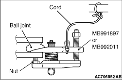
  • To prevent the ball joint thread damage, only loosen the nut from the ball joint (do not remove it), then disconnect the steering knuckle from the tie-rod using the special tool.
  • To prevent the special tool from dropping off, suspend it with a rope.
Install the ball joint remover (special tool: MB991897 or MB992011) as shown in the figure.

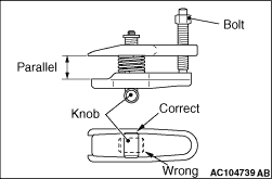
2.Turn the bolt and knob to make the special tool insert horizontal, then hand-tighten the bolt. After tightening, verify that the insert is still horizontal.
note To adjust the special tool jaws to be parallel, set the knob as shown in the figure so that it functions as a fulcrum of the jaws.

<<B>> A/C COMPRESSOR ASSEMBLY REMOVAL


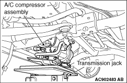
Displace the compressor assembly from the front axle No.1 crossmember, then support it using the transmission jack. However, do not remove the A/C pipes.

<<C>> STEERING COLUMN SHAFT DISCONNECTION


1.Remove the steering column bolt connecting steering gear to steering column assembly.
2.Disconnect the steering gear from the steering column assembly while sliding the shaft A to the shaft B with the clip claw as shown in the figure is pinched.

<<D>> STEERING GEAR & LINKAGE ASSEMBLY REMOVAL


Check that hoses and wiring harnesses are not caught, and then remove the steering gear & linkage assembly from between the stabilizer bar LH-side and the body.

INSTALLATION SERVICE POINTS


>>A<< STEERING JOINT COVER INSTALLATION


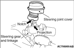
1.Install so that the notching of steering joint cover is aligned with the projection of steering gear & linkage assembly.

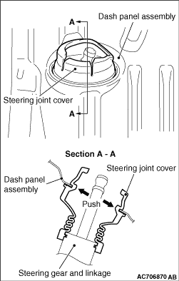
2.Pull the steering joint cover from the vehicle interior, and securely install it to the dash panel assembly as shown in the figure.

>>B<< STEERING COLUMN BOLT (STEERING COLUMN SHAFT ASSEMBLY AND STEERING GEAR & LINKAGE CONNECTION) INSTALLATION


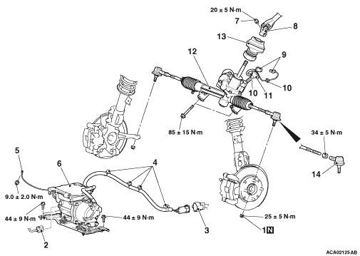
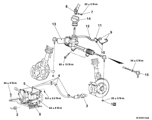
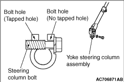
Insert the steering column bolt from the no-thread cutting bolt hole and tighten it to the specified torque.
Tightening torque: 20 ± 5 N·m