|
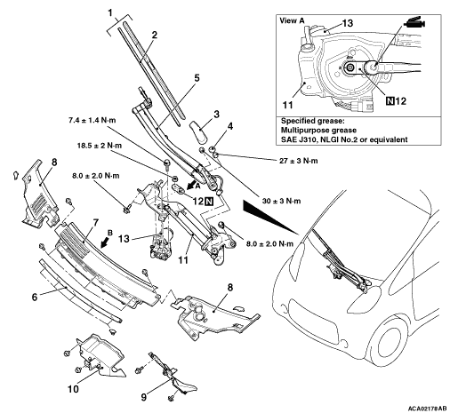
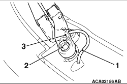
Remove the wiper arm (main arm and sub arm) in the order shown in the figure.
1.Washer nozzle hose
2.Main arm
3.Sub arm
|
|
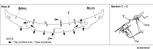
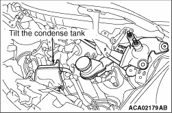
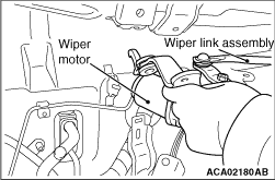
1.Remove the deck garnish, the wiper cover, the air duct, etc.Remove the 12V-battery
and the condense tank bracket.Tilt the condense tank as shown to ensure working space.
|
|
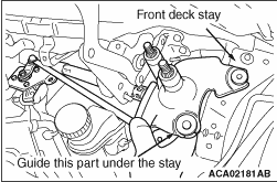
2.Unclip the die-casting at the electric motor side.
|
|
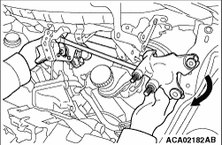
3.While pushing the die-casting at the pivot forwards, turn it so that the upper installation
point is positioned uppermost.In addition, guide the lower installation point under the front deck
stay.
|
|
4.Turn the windshield wiper link assembly further until the pivot faces down.
|
|
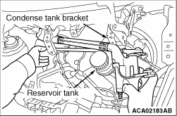
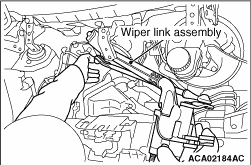
5.Pull out the windshield wiper link assembly between the deck garnish bracket and the
reservoir tank while taking care not to hit the assembly against the bottom of the condense
tank bracket.
|
|
6.Pulled-out condition.Installation is performed in reverse sequence.
|
|
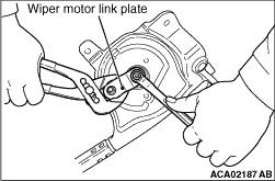
1.Remove the brake oil reservoir tank.Draw the tank aside with the hose connected, and
suspend it from the body.
2.Remove the condenser tank bracket A.Refer to GROUP 55, Heater Hose Removal and Installation  . .
3.Counter the wiper motor link plate, and remove from the wiper motor shaft.
4.Remove the wiper motor from the wiper link assembly.
|
|
|
1.Confirm that the wiper motor has set to automatic stop position (refer to ).
|
|
2.
| caution |
Wiper link rod plate at left end should be located as shown in the illustration
(dotted line shows incorrect location).
|
Assemble the wiper motor to windshield wiper link.
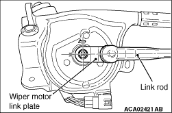
3.Set the wiper motor link plate onto the wiper motor shaft; aligning the plate to the
windshield wiper link as shown in the illustration.
4.Tighten the attaching nut of wiper motor link plate and wiper motor shaft. Use an
appropriate tool to counter-hold the plate to prevent it from turning.
5.Apply grease to the inside of link rod joint (as required) and connect the link rod
to wiper motor link plate.
|
|
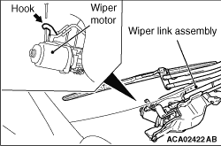
| caution |
Install the left hook of wiper link assembly (shown in the figure)
to the body securely.
|
|
|
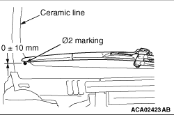
Install the wiper arm and blade assembly at the specified positions.
(A): Φ 2 marking ± 10 mm
|
|
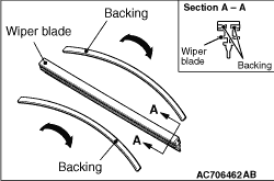
| caution |
Use a curved backing like that shown for the backing of a wiper blade to ensure sustained
wiper wiping performance.
|
|