|
|
Q.
Is diagnosis code set?
|
|
|
 Inspection chart for diagnosis code (Refer to Inspection chart for diagnosis code (Refer to  ). ).
|
|
|
|
|
|
- EV-ECU Data list reference table (Refer to ).
- Item 207: OBC connecting signal
|
|
|
Q.
Is the check result normal?
|
|
|
- Check Charging Cable (Refer to ).
|
|
|
Q.
Is the check result normal?
|
|
|
 Replace the charging cable. Replace the charging cable.
|
|
|
|
|
|
Q.
Are the check results normal?
|
|
|
Repair or replace the connector.
|
|
|
|
|
|
- Check signal line for open circuits, short circuits to earth and damage.
|
|
|
Q.
Is the check result normal?
|
|
|
Repair the damaged harness wire.
|
|
|
|
|
|
- Check earthing line for short circuit to earth.
|
|
|
Q.
Is the check result normal?
|
|
|
Repair the damaged harness wire.
|
|
|
|
|
|
- Check earthing line for open circuit and damage.
|
|
|
Q.
Is the check result normal?
|
|
|
Repair the damaged harness wire.
|
|
|
|
|
|
Q.
Does the trouble symptom persist?
|
|
|
Intermittent malfunction (Refer to GROUP 00 - How to Use Troubleshooting/Inspection
Service Points - How to Cope with Intermittent Malfunctions ).
|
|
|
|
|
|
Q.
Are the check results normal?
|
|
|
Repair or replace the connector.
|
|
|
|
|
|
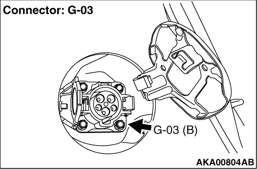
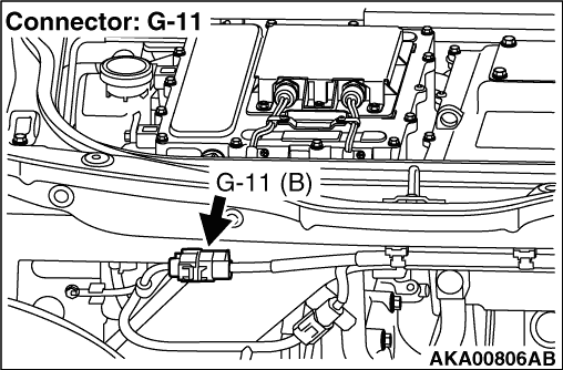
- Check and repair harness between G-03 (terminal No.
1) regular charging connector and G-11 (terminal No. 1) on board charger/DC-DC converter connector.
- Check and repair harness between G-03 (terminal No. 2) regular charging connector
and G-11 (terminal No. 2) on board charger/DC-DC converter connector.
- Check power supply line for open circuit.
|
|
|
Q.
Are the check results normal?
|
|
|
Repair the damaged harness wire.
|
|
|
|
|
|
Q.
Does the trouble symptom persist?
|
|
|
Replace the on board charger/DC-DC converter.
|
|
|
|
|
|
Intermittent malfunction (Refer to GROUP 00 - How to Use Troubleshooting/Inspection
Service Points - How to Cope with Intermittent Malfunctions ).
|
|
|
|