
|
1.Turn the crankshaft clockwise, and remove the timing belt rear cover mounting bolts shown in the figure from the gap of the camshaft sprocket.
|
|
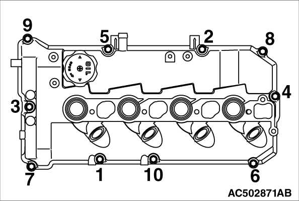
2.In the order shown in the figure, loosen the rocker cover assembly mounting bolts, and then remove the rocker cover assembly.
|

|
1.Install the nozzle gasket, fuel injector, pivot boss, and injector supporter to the cylinder head as shown in the figure.
2.Apply a small amount of engine oil to the seat surface and thread of injector holder bolt, and then temporarily tighten the bolt to the cylinder head.
3.Set the fuel leak-off gasket to the fuel leakage pipe, and temporarily tighten to the fuel injector and to the cylinder head using the eye bolt.
4.Tighten the eye bolt of the fuel injector side to the specified torque.
Tightening torque: 15 ± 2 N·m
5.Tighten the eye bolt of the cylinder head side to the specified torque.
Tightening torque: 15 ± 2 N·m
6.Tighten the injector holder bolt to the specified torque.
Tightening torque: 10 ± 1 N·m
|

|
7.
| caution |
- If the bolt is tightened less than the specified lower limit of 120 degree angle, the bolt may become loose. Be sure to tighten correctly.
- If the bolt is tightened in excess of the specified upper limit of 125 degree angle, loosen the nut completely and repeat the entire procedures.
|
Using special tool angle gauge (MB991614), tighten the injector holder bolt in the illustrated sequence by a further 120 to 125 degree angle.
|

|
Apply specified sealant to portions indicated in illustration.
Specified sealant: 3M ATD Part No. 8660 or equivalent
|

|
1.Apply specified sealant to portions indicated in illustration.
Specified sealant: 3M ATD Part No. 8660 or equivalent
2.Install the rocker cover assembly to the cylinder head.
|

|
3.Tighten the cylinder head assembly mounting bolt to the specified torque in the order shown in the figure.
Tightening torque: 3.0 ± 1.0 N·m
4.Again, tighten the cylinder head assembly mounting bolt to the specified torque in the order shown in the figure.
Tightening torque: 10 ± 2 N·m
|


|
Apply engine oil to the oil seal outer surface and drive in with a socket wrench.
|

