|
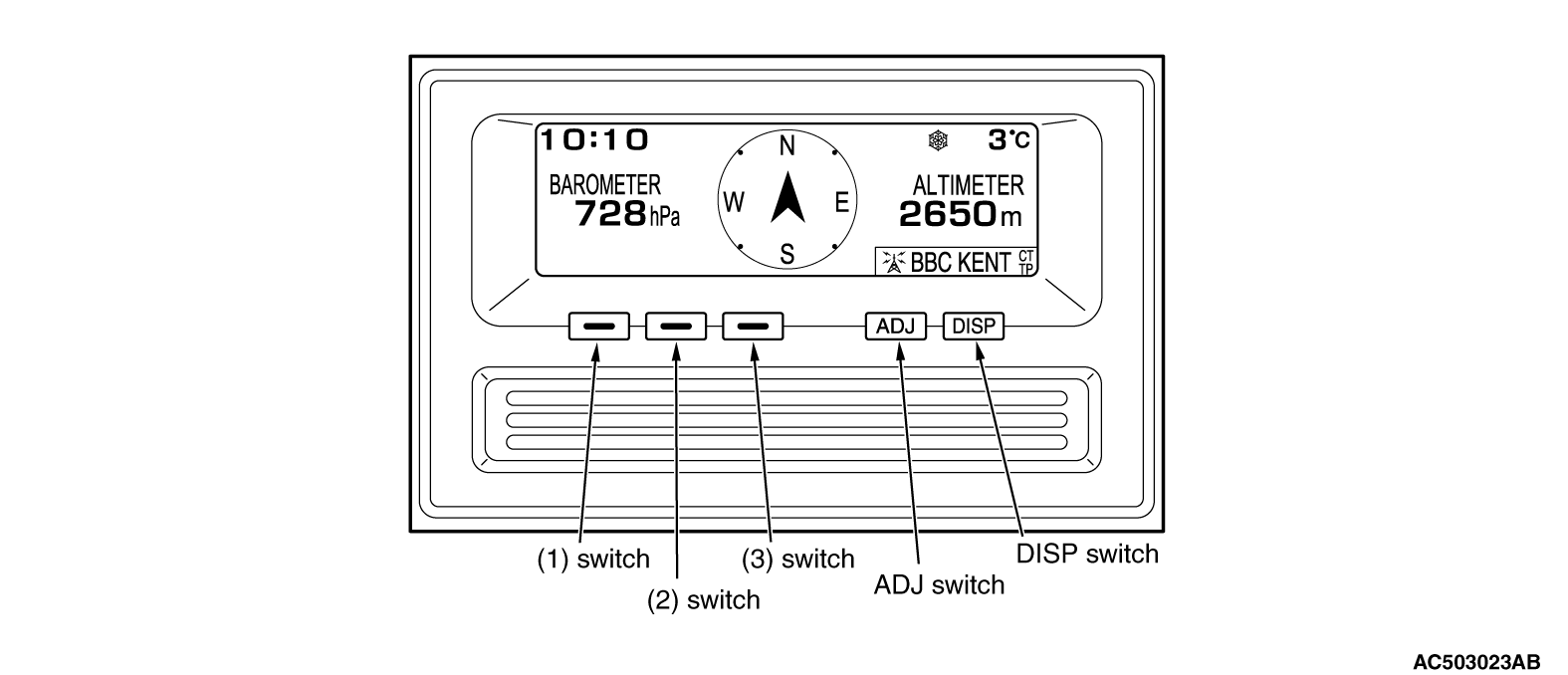
1.Turn the ignition switch to the LOCK (OFF) position, and then while pressing and holding
the "ADJ" switch, turn the ignition switch to the ACC position. After the "ADJ" switch has been
pressed continuously for 5 seconds or longer, the reception signal sound (beep) will sound,
and at the same time the service function will start up and the first menu of the service mode
screen will be displayed
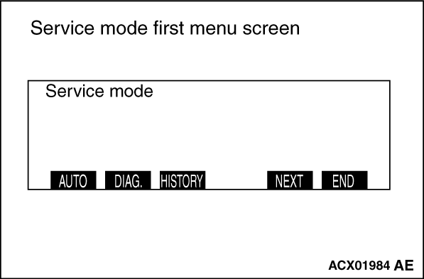
2.When function switch 1(AUTO) is pressed at the 1st menu of the service mode screen,
the mode is switched to the automatic mode. When function switch 2 (DIAG) is pressed, the mode
is switched to diagnosis mode. When function switch 3 (HISTORY) is pressed, the mode is switched
to history mode. Moreover, when "ADJ" switch,
|
|
1.When function switch 1 (AUTO) is pressed at the 1st menu of the service mode screen, the
mode is switched to automatic checking mode. At this time, a display will appear to prompt you
to turn the ignition switch to the ON position
2.When the ignition switch is turned to the ON position, communication and wiring check
is carried out
|
|
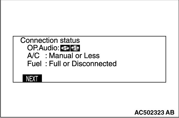
3.When the communication check is completed, the communication and wiring check results
are displayed on the screen.
Item
|
Display example
|
Contents or condition
|
OP. Audio
|
Icon of audio communicating with RV meter
|
-
|
A/C
|
AUTO
|
-
|
Manual or Less
|
Communication error
|
Fuel
|
OK
|
-
|
Full or Disconnected
|
Communication error
|
| note |
"Manual or Less" is normally displayed for A/C.(meaning that it is not connected)
|
|
|
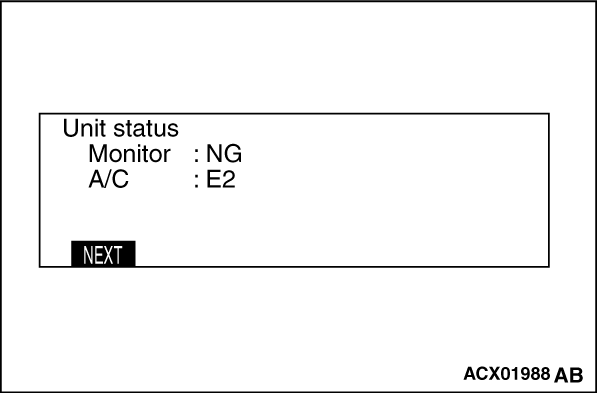
4.When function switch 1 (NEXT) is displayed at the previous screen, the status of unit
is displayed
Item
|
Display example
|
Contents or condition
|
Monitor
|
OK
|
-
|
A/C
|
NG
|
-
|
E1
|
Communication error
|
E2
|
Open circuit or disconnected
|
| note |
""E2" is normally displayed for A/C.(meaning that it is not connected)
|
|
|
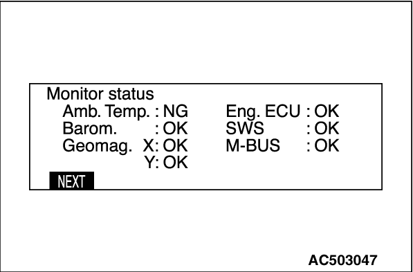
5.When function switch 1 (NEXT) is pressed at the previous screen, a list of monitor check
items and results is displayed.
Item
|
Display example
|
Contents or condition
|
Amb. Temp. (Outside air)
|
OK
|
-
|
Barom. (Barometric pressure)
|
OK
|
-
|
Geomag. X, Y
|
OK
|
-
|
Eng. ECU, SWS, ABS, M-BUS
|
E1
|
Communication error
|
E2
|
Open circuit or disconnected
|
| note |
- "E2" is normally displayed for Eng.ECU.(meaning that it is not connected)
- For vehicles without ABS, E2 is normally displayed for ABS.(meaning that it is not
connected)
|
|
|
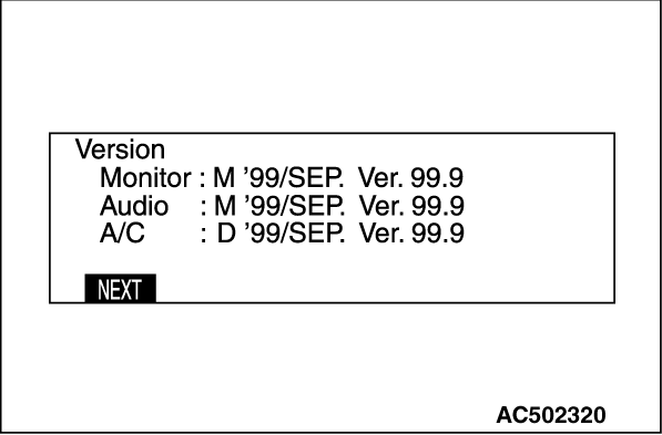
6.When function switch 1 (NEXT) is pressed at the previous screen, the version of monitor
and air conditioner is displayed.
For vehicles without air conditioner or with a manual air conditioner, the version is
not displayed.
| note |
M: Mitsubishi Electric
D: Denso
|
|
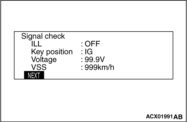
|
7.When function switch 1 (NEXT) is pressed at the previous screen, the status of vehicle
signal is displayed.
- ILL: ON or OFF
- Key position: "ACC" or "IG"
- Voltage: Battery voltage
- VSS: Vehicle speed
|
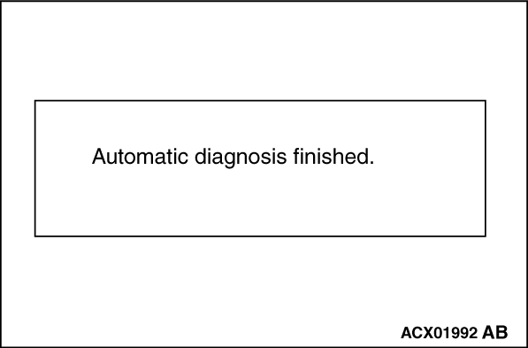
|
8.When function switch 1 (NEXT) is pressed at the previous screen, the mode is switched
to the previous mode screen of the service mode screen approximately 7 seconds after displaying
the message, "Automatic diagnosis finished."
|
|
1.From the 1st menu of the service mode screen, press function switch 2 (DIAG) to display
diagnosis mode.
|
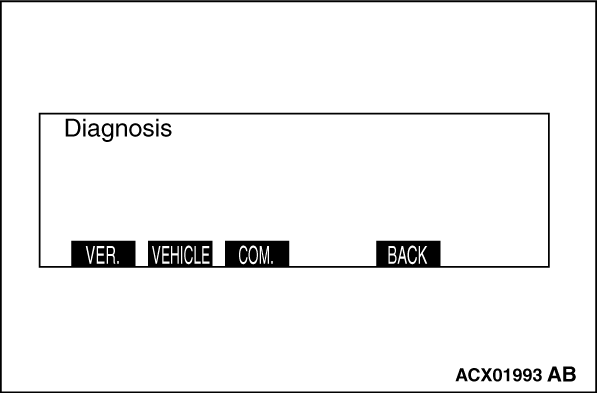
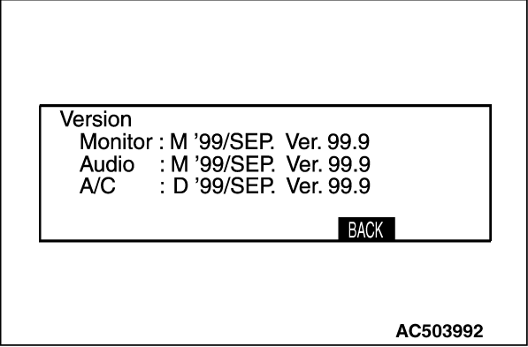
|
2.When function switch 1 (VER) is pressed, the version of monitor and air conditioner is
displayed
| note |
M: Mitsubishi Electric
D: Denso
|
|
|
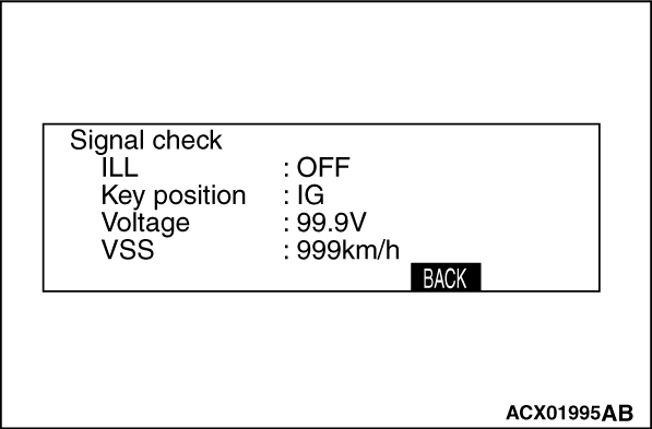
3.When function switch 2 (VEHICLE) is pressed, the vehicle signal condition is displayed.
- ILL: ON or OFF
- Key position: "ACC" or "IG"
- Voltage: Battery voltage
- VSS: Vehicle speed
|
|
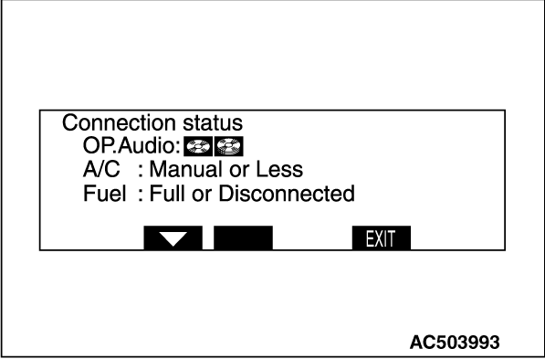
4.When function switch 3 (COM) is pressed, the results are displayed after communication
and wiring check is carried out.
Item
|
Display example
|
Contents or condition
|
OP. Audio
|
Icon of audio communicating with RV meter
|
-
|
A/C
|
AUTO
|
-
|
Manual or Less
|
Communication error
|
Fuel
|
OK
|
-
|
Full or Disconnected
|
Communication error
|
| note |
"Manual or Less" is normally displayed for A/C.(meaning that it is not connected)
|
|
|
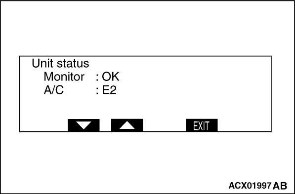
5.When function switch 2 (↓) at the previous screen, the status of unit is displayed.
|
|
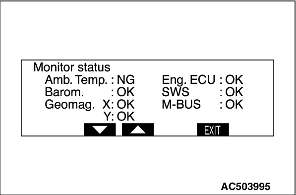
6.When function switch 2 (↓) at the previous screen, the status of monitor is displayed
Item
|
Display example
|
Contents or condition
|
Amb. Temp. (Outside air)
|
OK
|
-
|
Barom. (Barometric pressure)
|
OK
|
-
|
Geomag. X, Y
|
OK
|
-
|
Eng. ECU, SWS, ABS, M-BUS
|
E1
|
Communication error
|
E2
|
Open circuit or disconnected
|
| note |
- "E2" is normally displayed for Eng.ECU.(meaning that it is not connected)
- For vehicles without ABS, E2 is normally displayed for ABS.(meaning that it is not
connected)
|
|
|
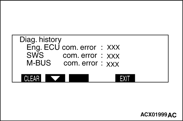
1.From the 1st menu of the service mode screen, press function switch 3 (HISTORY) to display
history mode.
2.When function switch 1 (CLEAR) is pressed, the number of errors is erased. When the
function switch 2 (↓) is pressed, the mode is switched to the 2nd menu of history mode.
Item
|
Display example
|
Contents or condition
|
Engine-ECU
(Powertrain control module)
SWS
M-BUS
|
000
|
Number of communication errors
|
|
|
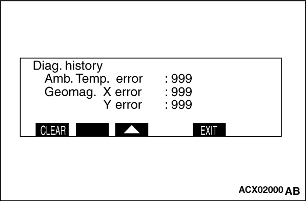
3.When function switch 1 (CLEAR) is pressed, the number of errors is erased. When the function
switch 3 (↑) is pressed, the mode is switched to the 1nd menu of history mode.
Item
|
Display example
|
Contents or condition
|
Amb. Temp
Barom.
Geomag. X, Y
|
000
|
Number of connection errors
|
|
|
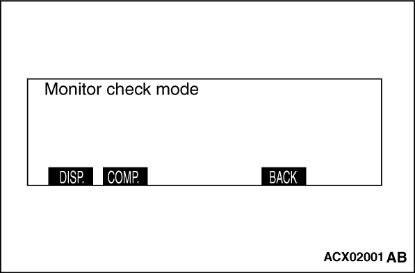
1.When function switch 1 (MONITOR) is pressed at the 2nd menu of the service mode screen,
the mode is switched to monitor check mode. The following displays appear when the various function
switches are pressed.
|
|
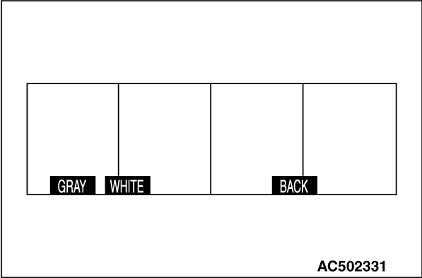
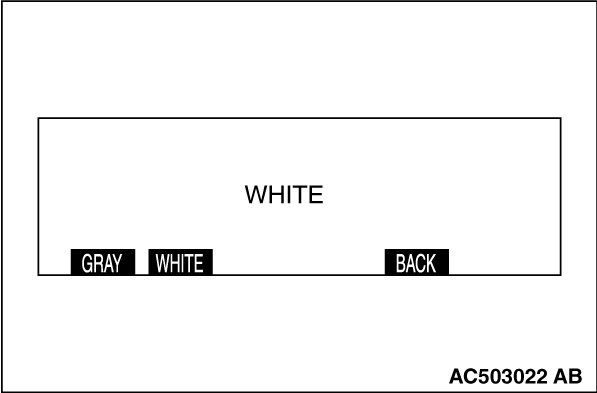
2.When function switch 1 (DISP) is pressed, the mode will be switched to display check mode.
- When function switch 2 (GRAY) is pressed, the grey scale screen is displayed.
- When function switch 3 (WHITE) is pressed, the white screen is displayed.
|
|
3.When function switch 2 (COMP) is pressed at the previous screen, the mode is switched
to geomagnetic sensor mode.
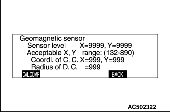
- At geomagnetic sensor mode, outputs in X- and Y-axes of the geomagnetic sensor,
the circular bearing coordinate, and the radius are displayed.
- When function switch1 (CAL.COMP) is pressed at the previous screen, the message shown
in the illustration is displayed, and then when calibration has been completed, the circular
bearing coordinate screen is displayed.
|
|
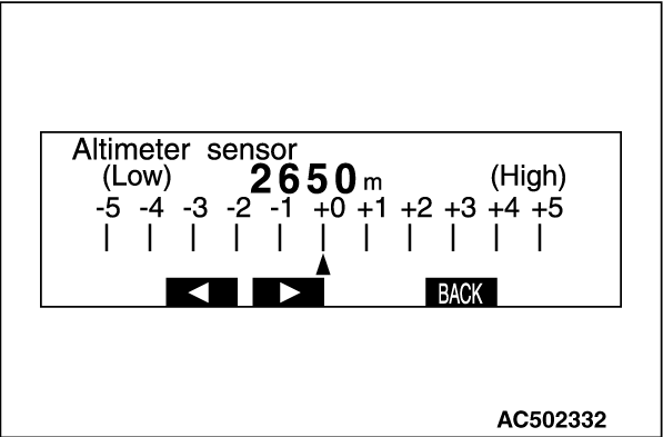
4.When function switch3 (ALTI) is pressed, the mode is switched to altitude correction mode
- When function switch 2 (←) is pressed, the altitude
is corrected downwards, and after approximately 5 seconds, the correction results are displayed
in the altitude correction column.
- When function switch 3 (→) is pressed, the altitude is corrected upwards,
and after approximately 5 seconds, the correction results are displayed in the altitude correction column
- When "ADJ" switch (BACK) is pressed, the mode is switched to monitor check mode
screen.
|
|
1.Press the "ADJ" switch with the ignition switch at "LOCK" (OFF) position, and while keeping
on pressing, turn the ignition switch to the "ACC" or "ON" position. When the "ADJ" switch is
pressed continuously for more than five seconds, the service function is activated at the same
time with the reception signal (pip sound) and the first menu screen of the service mode is
displayed.
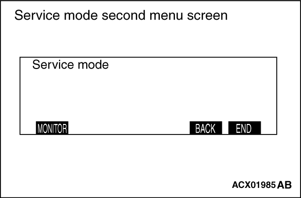
2.Press the "ADJ" switch (next).
The screen changes to the service mode second menu screen.
|
|
3.Press the function switch 1 (MONITOR) on the service mode second menu screen.
The screen is switched to the monitor check mode.
|
|
4.Press the function switch 2 (COMP.).
- <Normal case that the body is not magnetized>
The geomagnetic sensor mode screen is displayed. Each of X- and Y-outputs of the geomagnetic
sensor, center coordinates, and radius of the direction circle are displayed. For degeomagnetization,
refer to  .
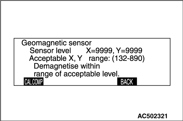
- <Case that the body is magnetized>
If the sensor value is outside the range between 450 and 580, it is meant that the body
is magnetized. The screen that calls upon to demagnetize the body stating "Demagnetize within
range of acceptable level" is displayed. In this case, it is necessary to demagnetize the body
and to correct the geomagnetic sensor. Refer to on-vehicle service-vehicle magnetic compensation .
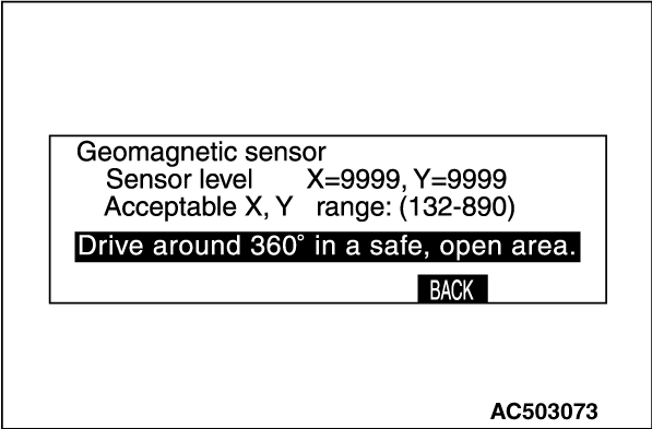
- When function switch 1 [CAL.COMP]
is pressed at the previous screen,
a message of urging rotation compensation is displayed. For the method of magnetization compensation
by rotation, refer to .
|
|
|
The service mode is released by pressing the "DISP" switch (END) is pressed on the service
mode first screen or the service mode second screen, or by turning the ignition switch to the
"LOCK" (OFF) position.
|
|
|
When the battery cable is disconnected, the stored data may disappear. In that case, the
system connection should be checked using the procedure described below
|
|
|
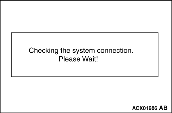
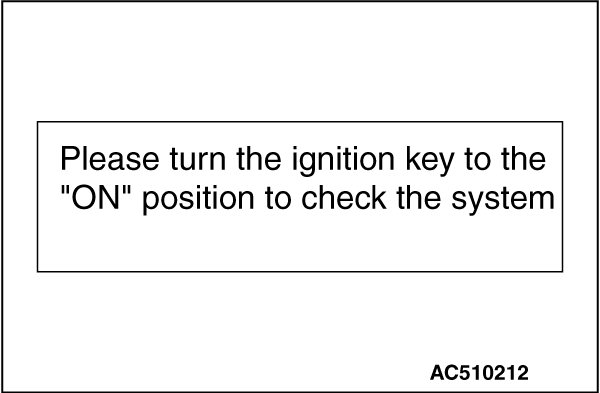
When the connection data has disappeared, turning the ignition key to "ACC" position will
make the following message appear.
|
|
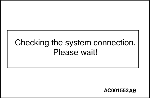
1.Start the engine (or turn the ignition key to "ON" position).
|
|
2.When the engine is started or when the ignition key is in the "ON" position, the monitor
will display the message.
|
|
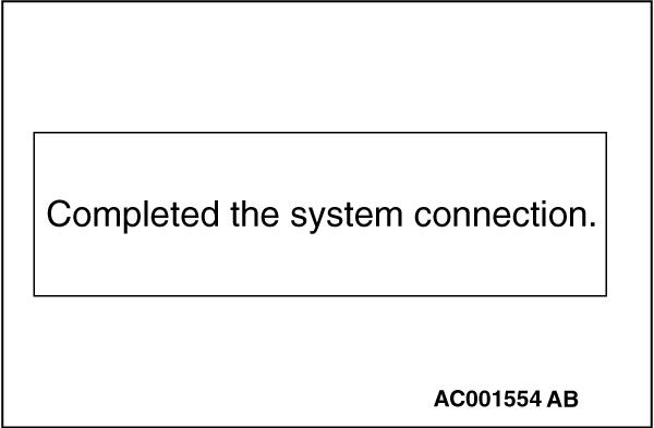
3.After a short while the system will beep. When the connection is completed, the message
will be displayed.
|