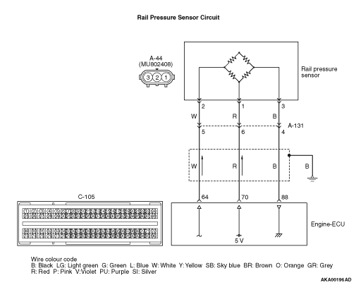
|
|
- Refer to Data List Reference Table
 . .
- Item 63: Rail pressure sensor
|
|
|
Q.
Is the check result normal?
|
|
|
 Intermittent malfunction (Refer to GROUP 00 - How to Use Troubleshooting/Inspection Service Points - How to Cope with Intermittent Malfunctions ). Intermittent malfunction (Refer to GROUP 00 - How to Use Troubleshooting/Inspection Service Points - How to Cope with Intermittent Malfunctions ).
|
|
|
|
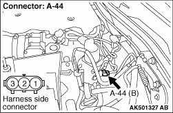
|
Q.
Is the check result normal?
Go to Step 3.
 Repair or replace the connector. Repair or replace the connector.
|
|
- Disconnect connector, and measure at harness side.
- Resistance between terminal No. 3 and earth.
OK: Continuity (2 Ω or less)
Q.
Is the check result normal?
Go to Step 7.
Go to Step 4.
|

|
Q.
Is the check result normal?
Go to Step 5.
Repair or replace the connector.
|
|
| note |
Before checking harness, check intermediate connector A-131, and repair if necessary.
|
- Check earthing line for open circuit.
Q.
Is the check result normal?
Go to Step 6.
Repair the damaged harness wire.
|
|
|
- Refer to Data List Reference Table .
- Item 63: Rail pressure sensor
|
|
|
Q.
Is the check result normal?
|
|
|
Intermittent malfunction (Refer to GROUP 00 - How to Use Troubleshooting/Inspection Service Points - How to Cope with Intermittent Malfunctions ).
|
|
|
|
|
|
Replace the engine-ECU. When the engine-ECU is replaced, write the chassis number (Refer to GROUP 00 - Precautions Before Service - How to Perform Chassis Number Writing ). After replacing the engine-ECU, register the injector identification code and learn fuel injection (Refer to GROUP 00 - Precautions Before Service - What The Common Rail Engine Learns ). After registering the injector identification code, the vehicle equipped with the DPF carries out the forcible DPF regeneration. (Refer to GROUP 17 - Emission Control - Diesel Particulate Filter (DPF) System - Forcible DPF Regeneration ).
|
|
|
|
|
|
- Refer to Data List Reference Table .
- Item 63: Rail pressure sensor
|
|
|
Q.
Is the check result normal?
|
|
|
Intermittent malfunction (Refer to GROUP 00 - How to Use Troubleshooting/Inspection Service Points - How to Cope with Intermittent Malfunctions ).
|
|
|
|
|
|
Replace the common rail assembly.
|
|
|
|