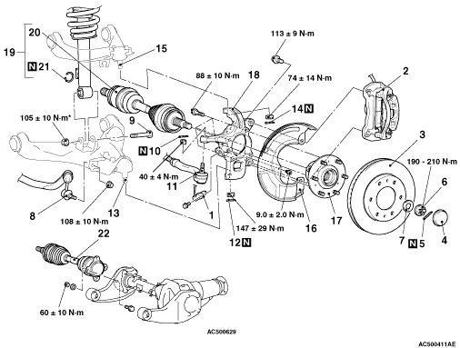
REMOVAL AND INSTALLATION


caution
  • *: Indicates parts which should be temporarily tightened, and then fully tightened with the vehicle on the earth in an unladen condition.
Pre-removal Operation
  • Under Cover Removal (Refer to GROUP 51, Under Cover ).
  • Gear Oil Draining (Refer to ).

Post-installation Operation
  • Press the dust cover with a finger to check whether the dust cover is cracked or damaged.
  • Gear Oil Supplying (Refer to ).
  • Under Cover Installation (Refer to GROUP 51, Under Cover ).
  • Wheel Alignment Check and Adjustment (Refer to GROUP 33, On-vehicle Service ).


Removal steps


1.
Front wheel speed sensor <Vehicles with ABS>
<<A>>

2.
Caliper assembly


3.
Brake disc


4.
Hub cap


5.
Split pin
<<B>>
>>A<<
6.
Driveshaft nut

>>A<<
7.
Washer


8.
Stabilizer link assembly to lower arm connection


9.
Shock absorber mounting bolt


10.
Split pin
<<C>>

11.
Tie rod end connection


12.
Split pin
<<C>>

13.
Lower arm ball joint connection


14.
Split pin
<<C>>

15.
Upper arm ball joint connection


16.
Dust cover


17.
Front hub assembly


18.
Knuckle


19.
LH driveshaft assembly


20.
LH driveshaft


21.
Circlip


22.
RH driveshaft assembly

REMOVAL SERVICE POINTS


<<A>> CALIPER ASSEMBLY REMOVAL


1.Remove the caliper assembly with brake hose.
2.Secure the removed caliper assembly with a wire or other similar material at a position where it will not interfere with the removal and installation of the hub assembly and knuckle.

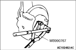
<<B>> DRIVESHAFT NUT REMOVAL


caution Do not apply pressure to wheel bearing by the vehicle weight to avoid possible damage when driveshaft nut is loosened.

Use special tool front hub and flange yoke holder (MB990767) to fix the hub and remove the driveshaft nut.

<<C>> TIE ROD END /LOWER ARM BALL JOINT /UPPER ARM BALL JOINT DISCONNECTION


caution
  • Do not remove the nut from the ball joint. Loosen it and use the special tool to avoid possible damage to ball joint threads.
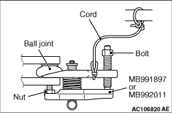
  • Hang the special tool with a cord to prevent from falling.

1.Install special tool ball joint remover (MB991897 or MB992011) as shown in the figure.

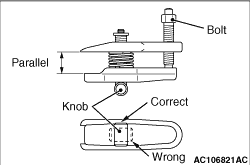
2.Turn the bolt and knob as necessary to make the jaws of special tool parallel, tighten the bolt by hand and confirm that the jaws are still parallel.
note When adjusting the jaws in parallel, make sure the knob is in the position shown in the figure.
3.Tighten the bolt with a wrench to disconnect the tie rod end.

INSTALLATION SERVICE POINT


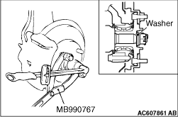
>>A<<WASHER/ DRIVESHAFT NUT INSTALLATION


caution Before securely tightening the driveshaft nuts, make sure there is no load on the wheel bearings. Otherwise the wheel bearings will be damaged.

1.Be sure to install the driveshaft washer in the specified direction.
2.Using special tool front hub and flange yoke holder (MB990767), tighten the driveshaft nut. At this time, tighten the driveshaft nut to the specified torque in expectation of final tightening.
Tightening torque: 190 - 210 N·m
3.If the pin hole do not align with the pins, tighten the driveshaft nut (less than 210 N·m) and find the nearest hole then bend the split pin to fit it.