Inspection Procedure 3: The ambient air temperature is not displayed normally. <Vehicles without auto A/C>
CIRCUIT OPERATION
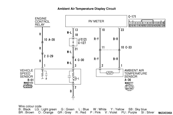
- For the vehicles without the auto A/C, the RV meter is connected
with the ambient air temperature sensor via harness wires. The ambient temperature is calculated
with the resistance reading of the ambient air temperature sensor. Also, the ambient temperature
displayed on the RV meter is corrected by the vehicle speed pulse signal of the vehicle speed
sensor.
- If the function type is set as 1 or 2 by mistake, the RV meter tries to acquire
the ambient temperature information from the A/C-ECU by the CAN communication, and
the ambient temperature cannot be displayed.
COMMENTS ON TROUBLE SYMPTOM
PROBABLE CAUSES
- Malfunction of the ambient air temperature sensor
- Damaged harness wires and connectors
DIAGNOSIS PROCEDURE |
STEP 1. Check the function type in the service mode. |
Check that the function type is set as 3 or 4 in the service mode. (Refer to  .) .) |
Q.
Is the check result satisfactory?
|
 Go to Step 2 Go to Step 2 |
|
 Set the function type again in the service mode, and recheck the trouble symptom.
(Refer to .) Set the function type again in the service mode, and recheck the trouble symptom.
(Refer to .) |
|
STEP 2. Check the RV meter. |
| Check that the average vehicle speed and the average fuel consumption are displayed normally,
and check that the connection with the vehicle speed sensor is normal. |
Q.
Is the check result satisfactory?
|
| Go to Step 3 |
|
| Perform the troubleshooting, Inspection Procedure 2: "The drive information is
not displayed normally". (Refer to .) |
|
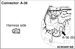
STEP 3. Check the following connector: A-36 ambient air temperature sensor |
 |
Q.
Is the check result normal?Go to Step 4Repair the defective connector. |
STEP 4. Check the ambient air temperature sensor. |
| Check the ambient air temperature sensor. |
Q.
Is the check result normal?
|
| Go to Step 5 |
|
| Replace the ambient air temperature sensor. |
|
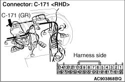
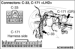
STEP 5. Check the following connector: C-171 RV meter connector |
  |
Q.
Is the check result normal?Go to Step 6Repair the defective connector. |
STEP 6. Check the harness wire between C-171 RV meter connector terminals No.10, 23 and A-36 ambient air temperature sensor connector terminals No.2, 1. |
 |
 |
Q.
Is the check result normal?Go to Step 7Repair the wiring harness. |
STEP 7. Recheck for malfunction. |
Q.
Is a malfunction eliminated?
|
| If no malfunctions are found in all steps, an intermittent malfunction is suspected.
Refer to GROUP 00, How to Use Troubleshooting/Inspection Service Points -
How
to Cope with Intermittent Malfunction . |
|
| Go to Step 8 |
|
STEP 8. Replace the ambient air temperature sensor temporarily, and check the trouble symptom. |
Q.
Is a malfunction eliminated?
|
| Replace the ambient air temperature sensor. |
|
| Replace the RV meter. |
|