


|
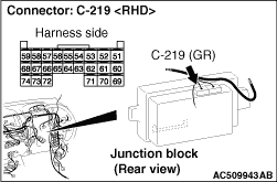
(1)Disconnect engine-ECU connector C-103 and ETACS-ECU connector C-219, and measure the voltage
at the harness side of diagnosis connector C-22.
(2)Connect the negative battery terminal, and turn the ignition switch to the ON position.
|

|
(3)Voltage between C-22 diagnosis connector terminal No.6 (CAN_H) and body earth
OK: 4.0 V or less
|

|
(4)Voltage between C-22 diagnosis connector terminal No.14 (CAN_L) and body earth
OK: 4.0 V or less
(5)Disconnect the negative battery terminal.
Q.
Is the check result normal?
 <Both of the measurement results show 4.0 V or less> Go to Step
23 . <Both of the measurement results show 4.0 V or less> Go to Step
23 .
 <Either of CAN_H line or CAN_L line the measurement
results show more than 4.0 V> Go to Step 2. <Either of CAN_H line or CAN_L line the measurement
results show more than 4.0 V> Go to Step 2.
|

|
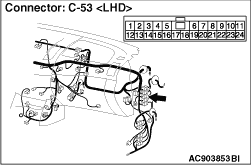
(1)Disconnect the intermediate connector, and measure at its male-side intermediate connector
(at the control wiring harness side).
(2)Connect the negative battery terminal, and turn the ignition switch to the ON position.
|

|
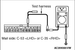
(3)Voltage between C-53 <LHD> or C-35 <RHD> intermediate connector terminal No.6
(CAN_H) and body earth
OK: 4.0 V or less
|
|
(4)Voltage between C-53 <LHD> or C-35 <RHD> intermediate connector terminal No.7
(CAN_L) and body earth
OK: 4.0 V or less
(5)Disconnect the negative battery terminal.
Q.
Is the check result normal?
<4.0 V or less> Go to Step 7.
<More than 4.0 V> Go to Step 3.
|


|
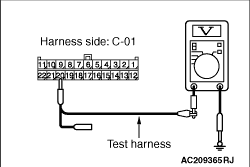
(1)Disconnect joint connector (CAN2), and measure at the wiring harness side.
(2)Connect the negative battery terminal, and turn the ignition switch to the ON position.
|

|
(3)Voltage between C-01 joint connector (CAN2) terminal No.9 (CAN_H) and body earth <LHD>
OK: 4.0 V or less
|

|
(4)Voltage between C-01 joint connector (CAN2) terminal No.10 (CAN_H) and body earth <RHD>
OK: 4.0 V or less
|
|
(5)Voltage between C-01 joint connector (CAN2) terminal No.20 (CAN_L) and body earth <LHD>
OK: 4.0 V or less
|

|
(6)Voltage between C-01 joint connector (CAN2) terminal No.21 (CAN_L) and body earth <RHD>
OK: 4.0 V or less
(7)Disconnect the negative battery terminal.
Q.
Is the check result normal?
YES <M/T> : <4.0 V or less> Repair intermediate connector C-53 <LHD>
or C-35 <RHD>, or the wiring harness between joint connector (CAN2) and intermediate connector
C-53 <LHD> or C-35 <RHD>.
YES <A/T> : <4.0 V or less> Go to Step 4. : <4.0 V or less> Go to Step 4.
NO : <More than 4.0 V> Repair the wiring harness between joint connector
(CAN2) and the engine-ECU connector.
|
|
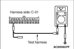
(1)Disconnect joint connector (CAN2), and measure at the wiring harness side.
(2)Connect the negative battery terminal, and turn the ignition switch to the ON position.
|

|
(3)Voltage between C-01 joint connector (CAN2) terminal No.10 (CAN_H) and body earth <LHD>
OK: 4.0 V or less
|

|
(4)Voltage between C-01 joint connector (CAN2) terminal No.9 (CAN_H) and body earth <RHD>
OK: 4.0 V or less
|
|
(5)Voltage between C-01 joint connector (CAN2) terminal No.21 (CAN_L) and body earth <LHD>
OK: 4.0 V or less
|

|
(6)Voltage between C-01 joint connector (CAN2) terminal No.20 (CAN_L) and body earth <RHD>
OK: 4.0 V or less
(7)Disconnect the negative battery terminal.
Q.
Is the check result normal?
<4.0 V or less> Repair intermediate connector C-53 <LHD>
or C-35 <RHD>, or the wiring harness between joint connector (CAN2) and the intermediate connector
C-53 <LHD> or C-35 <RHD>.
<More than 4.0 V> Go to Step 5.
|


|
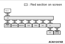
(1)Disconnect A/T-ECU connector C-20, and diagnose by using the M.U.T.-III.
|
|
(2)Diagnose CAN bus lines, and check if M.U.T.-III screen is as shown in the illustration.
Q.
Does M.U.T.-III screen correspond to the illustration?
Repair the wiring harness between joint connector (CAN2) and the A/T-ECU
connector.
Check the A/T-ECU connector, and repair if necessary. If the A/T-ECU
connector is in good condition, go to Step 6.
|
|
|
Diagnose CAN bus lines, and check if M.U.T.-III screen shows normal state.
|
|
|
Q.
Is the check result normal?
|
|
|
The trouble can be an intermittent malfunction (Refer to GROUP 00 - How
to use Troubleshooting/inspection Service Points - How to Cope with Intermittent
Malfunction  ). ).
|
|
|
|
|
|
Check the A/T-ECU connector, and repair if necessary. If the A/T-ECU
connector is in good condition, replace the A/T-ECU.
|
|
|
|

|
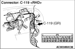
(1)Disconnect joint connector (CAN1), and measure at the wiring harness side.
(2)Connect the negative battery terminal, and turn the ignition switch to the ON position.
|

|
(3)Voltage between C-119 joint connector (CAN1) terminal No.9 (CAN_H) and body earth
OK: 4.0 V or less
|

|
(4)Voltage between C-119 joint connector (CAN1) terminal No.20 (CAN_L) and body
earth
OK: 4.0 V or less
(5)Disconnect the negative battery terminal.
| caution |
Strictly observe the specified wiring harness repair procedure.
For details refer to .
|
Q.
Is the check result normal?
<4.0 V or less> Go to Step 8.
<More than 4.0 V> Repair the wiring harness between joint connector
(CAN1) and the ETACS-ECU connector.
|
|
(1)Disconnect joint connector (CAN1), and measure at the wiring harness side.
(2)Connect the negative battery terminal, and turn the ignition switch to the ON position.
|

|
(3)Voltage between C-119 joint connector (CAN1) terminal No.7 (CAN_H) and body earth
OK: 4.0 V or less
|

|
(4)Voltage between C-119 joint connector (CAN1) terminal No.18 (CAN_L) and body
earth
OK: 4.0 V or less
(5)Disconnect the negative battery terminal.
| caution |
Strictly observe the specified wiring harness repair procedure.
For details refer to .
|
Q.
Is the check result normal?
YES <vehicles without ABS, ASTC and A/C> : <4.0 V or less> Go to Step 22.
YES <vehicles with ABS> : <4.0 V or less> Go to Step 10.
YES <vehicles with ASTC> : <4.0 V or less> Go to Step 13.
YES <vehicles without ABS and ASTC, and with A/C> : <4.0 V or less> Go to Step 20.
NO : <More than 4.0 V> Go to Step 9.
|

|
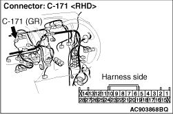
(1)Disconnect RV meter connector C-171, and diagnose by using the M.U.T.-III.
|
|
(2)Diagnose CAN bus lines, and check if M.U.T.-III screen is as shown in the illustration.
Q.
Does M.U.T.-III screen correspond to the illustration?
Repair the wiring harness between joint connector (CAN1) and the RV meter connector.
Check the RV meter connector, and repair if necessary. If the RV meter connector
is in good condition, repair the RV meter power supply circuit. (Refer to GROUP 54A - RV
meter .)
|
|
(1)Disconnect joint connector (CAN1), and measure at the wiring harness side.
(2)Connect the negative battery terminal, and turn the ignition switch to the ON position.
|

|
(3)Voltage between C-119 joint connector (CAN1) terminal No.5 (CAN_H) and body earth
OK: 4.0 V or less
|

|
(4)Voltage between C-119 joint connector (CAN1) terminal No.16 (CAN_L) and body
earth
OK: 4.0 V or less
(5)Disconnect the negative battery terminal.
| caution |
Strictly observe the specified wiring harness repair procedure.
For details refer to .
|
Q.
Is the check result normal?
YES <vehicles without A/C> : <4.0 V or less> Go to Step 22.
YES <vehicles with A/C> : <4.0 V or less> Go to Step 20.
NO : <More than 4.0 V> Go to Step 11.
|

|
(1)Disconnect ABS-ECU connector A-01, and diagnose by using the M.U.T.-III.
|
|
(2)Diagnose CAN bus lines, and check if M.U.T.-III screen is as shown in the illustration.
Q.
Does M.U.T.-III screen correspond to the illustration?
Check the intermediate connector (C-13), and repair if necessary. If the intermediate
connector is in good condition, repair the wiring harness between joint connector (CAN1) and
the ABS-ECU connector.
Check the ABS-ECU connector, and repair if necessary. If the ABS-ECU connector
is in good condition, go to Step 12.
|
|
|
Diagnose CAN bus lines, and check if M.U.T.-III screen shows normal state.
|
|
|
Q.
Is the check result normal?
|
|
|
The trouble can be an intermittent malfunction (Refer to GROUP 00 - How
to use Troubleshooting/inspection Service Points - How to Cope with Intermittent
Malfunction ).
|
|
|
|
|
|
Check the ABS-ECU connector, and repair if necessary. If the ABS-ECU connector
is in good condition, replace the hydraulic unit assembly.
|
|
|
|
|
(1)Disconnect joint connector (CAN1), and measure at the wiring harness side.
(2)Connect the negative battery terminal, and turn the ignition switch to the ON position.
|
|
(3)Voltage between C-119 joint connector (CAN1) terminal No.5 (CAN_H) and body earth
OK: 4.0 V or less
|
|
(4)Voltage between C-119 joint connector (CAN1) terminal No.16 (CAN_L) and body
earth
OK: 4.0 V or less
(5)Disconnect the negative battery terminal.
| caution |
Strictly observe the specified wiring harness repair procedure.
For details refer to .
|
Q.
Is the check result normal?
<4.0 V or less> Go to Step 16.
<More than 4.0 V> Go to Step 14.
|
|
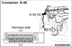
(1)Disconnect ASTC-ECU connector A-48, and diagnose by using the M.U.T.-III.
|
|
(2)Diagnose CAN bus lines, and check if M.U.T.-III screen is as shown in the illustration.
Q.
Does M.U.T.-III screen correspond to the illustration?
Check the intermediate connector (C-13), and repair if necessary. If the intermediate
connector is in good condition, repair the wiring harness between joint connector (CAN1) and
the ASTC-ECU connector.
Check the ASTC-ECU connector, and repair if necessary. If the ASTC-ECU connector
is in good condition, go to Step 15.
|
|
|
Diagnose CAN bus lines, and check if M.U.T.-III screen shows normal state.
|
|
|
Q.
Is the check result normal?
|
|
|
The trouble can be an intermittent malfunction (Refer to GROUP 00 - How
to use Troubleshooting/inspection Service Points - How to Cope with Intermittent
Malfunction ).
|
|
|
|
|
|
Check the ASTC-ECU connector, and repair if necessary. If the ASTC-ECU connector
is in good condition, replace the hydraulic unit assembly.
|
|
|
|
|
(1)Disconnect joint connector (CAN1), and measure at the wiring harness side.
(2)Connect the negative battery terminal, and turn the ignition switch to the ON position.
|

|
(3)Voltage between C-119 joint connector (CAN1) terminal No.3 (CAN_H) and body earth
OK: 4.0 V or less
|

|
(4)Voltage between C-119 joint connector (CAN1) terminal No.14 (CAN_L) and body
earth
OK: 4.0 V or less
(5)Disconnect the negative battery terminal.
| caution |
Strictly observe the specified wiring harness repair procedure.
For details refer to .
|
Q.
Is the check result normal?
<4.0 V or less> Go to Step 18.
NO : <More than 4.0 V> Go to Step 17.
|
|
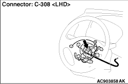
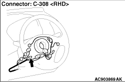
(1)Disconnect steering wheel sensor connector C-308, and diagnose by using the M.U.T.-III.
|
|
(2)Diagnose CAN bus lines, and check if M.U.T.-III screen is as shown in the illustration.
Q.
Does M.U.T.-III screen correspond to the illustration?
Repair the wiring harness between joint connector (CAN1) and the steering wheel
sensor connector.
Check the steering wheel sensor connector, and repair if necessary. If the steering
wheel sensor connector is in good condition, repair the steering wheel sensor power supply circuit.
|
|
(1)Disconnect joint connector (CAN1), and measure at the wiring harness side.
(2)Connect the negative battery terminal, and turn the ignition switch to the ON position.
|

|
(3)Voltage between C-119 joint connector (CAN1) terminal No.4 (CAN_H) and body earth
OK: 4.0 V or less
|

|
(4)Voltage between C-119 joint connector (CAN1) terminal No.15 (CAN_L) and body
earth
OK: 4.0 V or less
(5)Disconnect the negative battery terminal.
| caution |
Strictly observe the specified wiring harness repair procedure.
For details refer to .
|
Q.
Is the check result normal?
YES <vehicles without A/C> : <4.0 V or less> Go to Step 22.
YES <vehicles with A/C> : <4.0 V or less> Go to Step 20.
NO : <More than 4.0 V> Go to Step 19.
|


|
(1)Disconnect G and yaw rate sensor connector C-144, and diagnose by using the M.U.T.-III.
|
|
(2)Diagnose CAN bus lines, and check if M.U.T.-III screen is as shown in the illustration.
Q.
Does M.U.T.-III screen correspond to the illustration?
Repair the wiring harness between joint connector (CAN1) and the G and yaw rate
sensor connector.
Check the G and yaw rate sensor connector, and repair if necessary. If the G and
yaw rate sensor connector is in good condition, repair the G and yaw rate sensor power supply
circuit.
|
|
(1)Disconnect joint connector (CAN1), and measure at the wiring harness side.
(2)Connect the negative battery terminal, and turn the ignition switch to the ON position.
|

|
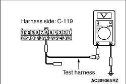
(3)Voltage between C-119 joint connector (CAN1) terminal No.6 (CAN_H) and body earth
OK: 4.0 V or less
|
|
(4)Voltage between C-119 joint connector (CAN1) terminal No.17 (CAN_L) and body
earth
OK: 4.0 V or less
(5)Disconnect the negative battery terminal.
| caution |
Strictly observe the specified wiring harness repair procedure.
For details refer to .
|
Q.
Is the check result normal?
<4.0 V or less> Go to Step 22.
<More than 4.0 V> Go to Step 21.
|
|
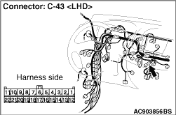
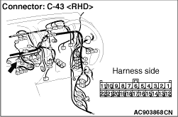
(1)Disconnect A/C-ECU connector C-43, and diagnose by using the M.U.T.-III.
|
|
(2)Diagnose CAN bus lines, and check if M.U.T.-III screen is as shown in the illustration.
Q.
Does M.U.T.-III screen correspond to the illustration?
Repair the wiring harness between joint connector (CAN1) and the A/C-ECU
connector.
Check the A/C-ECU connector, and repair if necessary. If the A/C-ECU
connector is in good condition, repair the A/C-ECU power supply circuit. (Refer to GROUP 55B .)
|
|
(1)Disconnect joint connector (CAN1), and measure at the wiring harness side.
(2)Connect the negative battery terminal, and turn the ignition switch to the ON position.
|

|
(3)Voltage between C-119 joint connector (CAN1) terminal No.10 (CAN_H) and body
earth
OK: Less than 1.0 V
|

|
(4)Voltage between C-119 joint connector (CAN1) terminal No.21 (CAN_L) and body
earth
OK: Less than 1.0 V
(5)Disconnect the negative battery terminal.
| caution |
Strictly observe the specified wiring harness repair procedure.
For details refer to .
|
Q.
Is the check result normal?
<Less than 1.0 V> Repair the intermediate connector, or the
wiring harness between joint connector (CAN1) and the intermediate connector C-53 <LHD>
or C-35 <RHD>.
<1.0 V or more> Repair the diagnosis connector, or the wiring
harness between joint connector (CAN1) and the diagnosis connector.
|
|
(1)Disconnect engine-ECU connector C-103 and diagnose by using the M.U.T.-III.
|
|
(2)Diagnose CAN bus lines, and check if M.U.T.-III screen is as shown in the illustration.
Q.
Does M.U.T.-III screen correspond to the illustration?
Go to Step 25.
Check the engine-ECU connector, and repair if necessary. If the engine-ECU connector
is in good condition, go to Step 24.
|
|
|
Diagnose CAN bus lines, and check if M.U.T.-III screen shows normal state.
|
|
|
Q.
Is the check result normal?
|
|
|
The trouble can be an intermittent malfunction (Refer to GROUP 00 - How
to use Troubleshooting/inspection Service Points - How to Cope with Intermittent
Malfunction ).
|
|
|
|
|
|
Check the engine-ECU connector, and repair if necessary. If the engine-ECU connector
is in good condition, replace the engine-ECU.
|
|
|
|
|
(1)Disconnect ETACS-ECU connector C-219, and diagnose by using the M.U.T.-III.
|
|
(2)Diagnose CAN bus lines, and check if M.U.T.-III screen is as shown in the illustration.
Q.
Does M.U.T.-III screen correspond to the illustration?
The trouble can be an intermittent malfunction (Refer to GROUP 00 - How
to use Troubleshooting/inspection Service Points - How to Cope with Intermittent
Malfunction ).
Check the ETACS-ECU connector, and repair if necessary. If the ETACS-ECU connector
is in good condition, go to Step 26.
|
|
|
Diagnose CAN bus lines, and check if M.U.T.-III screen shows normal state.
|
|
|
Q.
Is the check result normal?
|
|
|
The trouble can be an intermittent malfunction (Refer to GROUP 00 - How
to use Troubleshooting/inspection Service Points - How to Cope with Intermittent
Malfunction ).
|
|
|
|
|
|
Check the ETACS-ECU connector, and repair if necessary. If the ETACS-ECU connector
is in good condition, replace the ETACS-ECU.
|
|
|
|
