Inspection Procedure 30: No. 1 Exhaust Gas Temperature Sensor System <Vehicles with DPF>
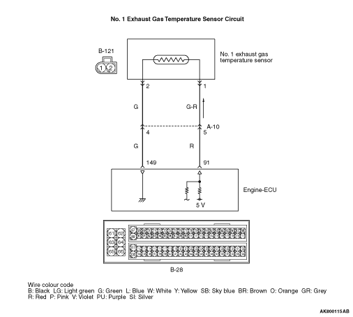
OPERATION
- A power voltage of 5 V is applied to the No. 1 exhaust gas temperature sensor
output terminal (terminal No. 1) from the engine-ECU (terminal No. 91).
- The power voltage is earthed to the engine-ECU (terminal No. 149) from the No. 1
exhaust gas temperature sensor (terminal No. 2).
FUNCTION
- The No. 1 exhaust gas temperature sensor converts the exhaust gas temperature
into a voltage and inputs the voltage signal to the engine-ECU.
- Engine-ECU uses this output voltage for DPF regeneration control.
- The No. 1 exhaust gas temperature sensor is a kind of resistor, which has characteristics
to increase its resistance as the exhaust gas temperature rises. Therefore, the sensor output voltage
varies with the exhaust gas temperature, and becomes upper as the exhaust gas temperature rises.
PROBABLE CAUSES
- Failed No. 1 exhaust gas temperature sensor
- Open/short circuit or harness damage in No. 1 exhaust gas temperature sensor circuit
or loose connector contact
- Failed engine-ECU
DIAGNOSIS PROCEDURE |
STEP 1. M.U.T.-III data list |
|
Q.
Is the check result normal?
|
 Intermittent malfunction (Refer to GROUP 00 - How to Use Troubleshooting/Inspection
Service Points - How to Cope with Intermittent Malfunctions Intermittent malfunction (Refer to GROUP 00 - How to Use Troubleshooting/Inspection
Service Points - How to Cope with Intermittent Malfunctions  ). ). |
|
 Go to Step 2 . Go to Step 2 . |
|
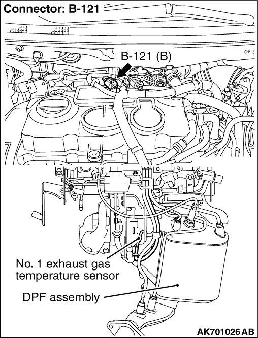
STEP 2. Connector check: B-121 No. 1 exhaust gas temperature sensor connector |
Q.
Is the check result normal?
|
| Go to Step 3 . |
|
| Repair or replace the connector. |
|
STEP 3. Check No. 1 exhaust gas temperature sensor itself. |
|
Q.
Is the check result normal?
|
| Go to Step 4 . |
|
| Replace the No. 1 exhaust gas temperature sensor. |
|
STEP 4. Perform voltage measurement at B-121 No. 1 exhaust gas temperature sensor connector. |
|
| OK: 4.5 - 4.9 V |
Q.
Is the check result normal?
|
| Go to Step 8 . |
|
| Go to Step 5 . |
|
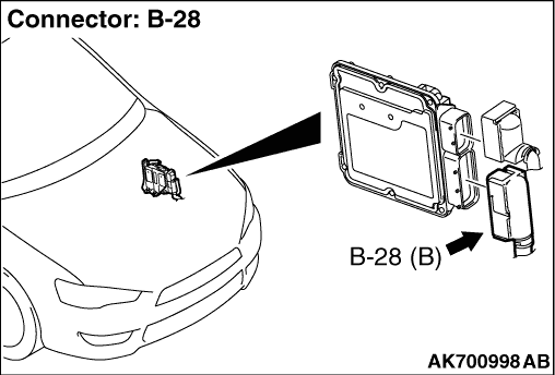
STEP 5. Connector check: B-28 engine-ECU connector. |
Q.
Is the check result normal?
|
| Go to Step 6 . |
|
| Repair or replace the connector. |
|
STEP 6. Check harness between B-121 (terminal No. 1) No. 1 exhaust gas temperature sensor connector and B-28 (terminal No. 91) engine-ECU connector. |
|
|
Q.
Is the check result normal?
|
| Go to Step 7 . |
|
| Repair the damaged harness wire. |
|
STEP 7. M.U.T.-III data list |
|
Q.
Is the check result normal?
|
| Intermittent malfunction (Refer to GROUP 00 - How to Use Troubleshooting/Inspection
Service Points - How to Cope with Intermittent Malfunctions ). |
|
| Replace the engine-ECU. |
|
STEP 8. Perform resistance measurement at B-121 No. 1 exhaust gas temperature sensor connector. |
|
| OK: Continuity (2 Ω or less) |
Q.
Is the check result normal?
|
| Go to Step 11 . |
|
| Go to Step 9 . |
|
STEP 9. Connector check: B-28 engine-ECU connector |
Q.
Is the check result normal?
|
| Go to Step 10 . |
|
| Repair or replace the connector. |
|
STEP 10. Check harness between B-121 (terminal No. 2) No. 1 exhaust gas temperature sensor connector and B-28 (terminal No. 149) engine-ECU connector. |
|
|
Q.
Is the check result normal?
|
| Go to Step 7 . |
|
| Repair the damaged harness wire. |
|
STEP 11. Connector check: B-28 engine-ECU connector. |
Q.
Is the check result normal?
|
| Go to Step 12 . |
|
| Repair or replace the connector. |
|
STEP 12. Check harness between B-121 (terminal No. 1) No. 1 exhaust gas temperature sensor connector and B-28 (terminal No. 91) engine-ECU connector. |
|
|
Q.
Is the check result normal?
|
| Go to Step 7 . |
|
| Repair the damaged harness wire. |
|