REMOVAL AND INSTALLATION


caution
  • When inserting the reservoir hose assembly, do not lubricate.
  • Perform with care that the foreign objects do not intrude into the hydraulic unit and hose joint.
Pre-removal operation
  • Rear wheel (RH) removal
  • Rear wheelhouse splash shield removal (Refer to GROUP 42A - Splash Shield .)
  • Quarter trim (RH) removal (Refer to GROUP 52A - Interior Trim .)

Post-installation operation
  • Bleeding (Refer to On-vehicle Service - ACD Bleeding .)
  • Quarter trim (RH) installation (Refer to GROUP 52A - Interior Trim .)
  • Rear wheelhouse splash shield installation (Refer to GROUP 42A - Splash Shield .)
  • Rear wheel (RH) installation


Removal steps


1.
ACD pressure tube assembly mounting bolt


2.
ACD pressure tube assembly and hydraulic unit connection


3.
Reservoir hose assembly and hydraulic unit connection


4.
Hydraulic unit connector connection


5.
Hydraulic unit bracket A, hydraulic unit, and hydraulic unit bracket B connecting bolt

>>B<<
6.
Hydraulic unit and hydraulic unit bracket B


7.
Hydraulic unit bracket B


8.
Hydraulic unit


9.
Hydraulic unit bracket A


10.
ACD pressure tube assembly

>>A<<
11.
Reservoir hose assembly


12.
Oil reservoir

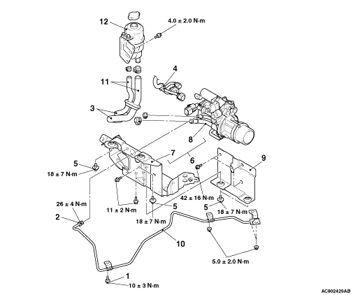
INSTALLATION SERVICE POINTS


>>A<< RESERVOIR HOSE ASSEMBLY INSTALLATION


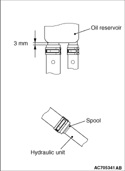
1.On the oil reservoir side, insert the hose to the position shown in the figure.
2.On the hydraulic unit side, insert the hose to the spool shown in the figure.

>>B<< HYDRAULIC UNIT AND HYDRAULIC UNIT BRACKET B INSTALLATION


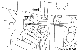
Insert the hook of hydraulic unit bracket B into the body panel, and tighten the mounting bolt.