INSPECTION PROCEDURE 3: Speed change with the paddle shift is impossible.
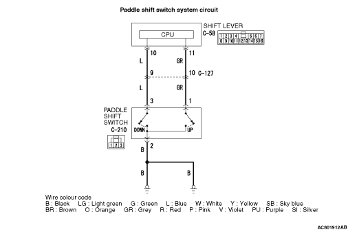


| caution | Whenever the ECU is replaced, ensure that the CAN bus lines are normal. |
COMMENTS ON TROUBLE SYMPTOM
PROBABLE CAUSES
- Malfunction of the paddle shift switch
- Damaged harness wires and connectors
- Malfunction of the shift lever-ECU
- Malfunction of TC-SST-ECU
DIAGNOSIS PROCEDURE |
STEP 1. M.U.T.-III CAN bus diagnostics. |
| Use M.U.T.-III to perform the CAN bus diagnosis. |
Q.
Is the check result normal?
|
 Go to Step 2. Go to Step 2. |
|
 Repair the CAN bus lines. (Refer to GROUP 54C - Troubleshooting Repair the CAN bus lines. (Refer to GROUP 54C - Troubleshooting  .) After repairing the CAN bus line, go to Step 2. .) After repairing the CAN bus line, go to Step 2. |
|
STEP 2. Paddle shift switch check |
| Refer to . |
Q.
Is the check result normal?
|
| Go to Step 3. |
|
| Replace the paddle shift assembly. (Refer to .) |
|
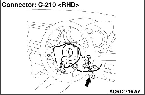
STEP 3. Measure the resistance at C-210 paddle shift switch connector. |
| Disconnect the connector, and measure the resistance between terminal No.2 and earth at the wiring harness side. |
| OK: Continuity exists. (2 Ω or less) |
Q.
Is the check result normal?
|
| Go to Step 6. |
|
| Go to Step 4. |
|
STEP 4. Paddle shift switch connector check: C-210 |
| Check for the contact with terminals. |
Q.
Is the check result normal?
|
| Go to Step 5. |
|
| Repair the defective connector. |
|
STEP 5. Check the wiring harness between C-210 paddle shift switch connector terminal No.2 and the body earth. |
| Check the earth line for open circuit. |
Q.
Is the check result normal?
|
| Go to Step 6. |
|
| Repair the wiring harness. |
|
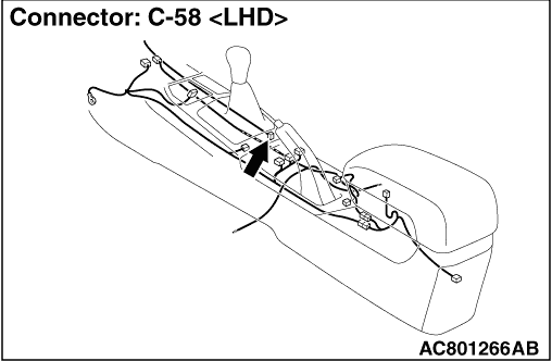
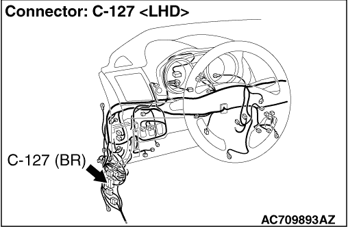
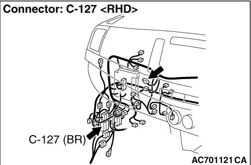
STEP 6. Inspection of the shift lever assembly connector, intermediate connector, and paddle shift switch connector: C-58, C-127, C-210 |
| Check for the contact with terminals. |
Q.
Is the check result normal?
|
| Go to Step 7. |
|
| Repair the defective connector. |
|
STEP 7. Check the wiring harness between C-210 paddle shift switch connector terminal No.1 and C-58 shift lever assembly connector terminal No.11, and between C-210 paddle shift switch connector terminal No.3 and C-58 shift lever assembly connector terminal No.10. |
| Check the output line for short or open circuit. |
Q.
Is the check result normal?
|
| Go to Step 8. |
|
| Repair the wiring harness. |
|
STEP 8. Trouble symptom recheck after replacing the shift lever assembly |
| (1)Replace the shift lever assembly. (Refer to .) |
| (2)Verify that the condition described by the customer exists. |
Q.
Does a malfunction take place again?
|
| Replace the TC-SST assembly. (Refer to .) |
|
| Intermittent malfunction. (Refer to GROUP 00 - How to Cope with Intermittent Malfunction .) |
|