|
|
After removing the strut tower bar, temporarily install the strut assembly.
|
|
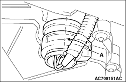
Rotate the section A of the connector 90° to the direction of the arrow to disconnect
the connector.
|
|
|
Remove the starter with its connector connected. Keep the starter fixed to the engine
side.
|
|
|
Only loosen the bolts from the engine and transmission assembly (do not remove).
|
|
|
1.Place a garage jack against the transmission case with a piece of wood in between
to support the engine and transmission assembly.
|
|
|
2.Operate the garage jack so that the engine and transmission assembly weight is not
applied to the transmission mounting insulator, and remove the transmission mounting bracket.
|

|
1.Remove the vacuum pipe assembly (refer to GROUP 14 - Water Hose and Water Pipe  ),
and install the engine hanger plate (Special tool: MB992201), then tighten the bolts to the
specified torque. ),
and install the engine hanger plate (Special tool: MB992201), then tighten the bolts to the
specified torque.
Tightening torque: 11± 1 N·m
|

|
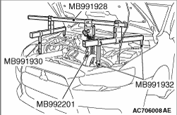
2.<When engine hanger (special tool MB991928) is used>
(1)
Assemble the engine hanger (special tool MB991928). (Set following
parts to the base hanger.)
- Slide bracket (HI)
- Foot x 4 (standard) (MB991932)
- Joint x 2 (90) (MB991930)
(2)
Set the feet of the special tool as shown in the figure.
|
|
| note |
Adjust the engine hanger balance by sliding the slide bracket (HI).
|
|
(3)
Set the chain to the engine hanger plate (Special tool: MB992201) to support the engine
and transmission assembly. Remove the garage jack, and then remove the transmission assembly
upper part coupling bolts that have been loosened previously.
|

|
3.<Engine mechanical hanger (special tool MB991895) is used>
(1)
Set the feet of the engine mechanical hanger (special tool MB991895) as shown in the figure.
|
|
| note |
Slide the front foot of the engine mechanical hanger (Special tool: MB991895) to balance
the engine hanger.
|
|
(2)
Set the chain to the engine hanger plate (Special tool: MB992201) to support the engine
and transmission assembly. Remove the garage jack, and then remove the transmission assembly
upper part coupling bolts that have been loosened previously.
|

|
Apply the specified grease to the flywheel spline section, O-ring, and spline section
of transmission assembly input shaft.
Grease
Brand name: Molykote BR2-Plus
|

|
Install the transmission mounting insulator stopper as shown in the figure.
|
|
|
1.Set the shift lever to the N position.
|

|
2.Operate the lever so that the shift control lever positioning mark is set to the N position.
|

|
3.Move the slider of the transmission control cable (transmission side) tip to the direction
A to pull up the lock piece to the direction B.
|

|
4.Align the transmission control cable and the shift control lever joint (positioning only,
do not connect), and firmly push down the lock piece to lock it. Then, connect the transmission
control cable and the shift control lever.
| note |
- The slider automatically returns to the fixed position by the spring.
- The lock position of transmission control cable is automatically adjusted by a spring.
|
|
