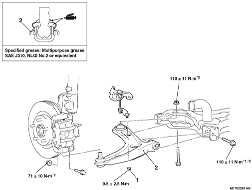
REMOVAL AND INSTALLATION


caution
  • The parts indicated by *1 indicates parts which should be temporarily tightened, and then fully tightened with the vehicle standing on the ground and the curb weight condition.
  • The parts indicated by *2 are the bolts/nuts with friction coefficient stabilizer. In removal, ensure there is no damage, clean dust and soiling from the bearing and thread surfaces, and tighten them to the specified torque.
Pre-removal OperationEngine Room Side Cover Removal (Refer to GROUP 51 - Under Cover ).
Post-installation Operation
  • Using Your Fingers, Press the Dust Cover to Check for a Crack or Damage.
  • Engine Room Side Cover Installation (Refer to GROUP 51 - Under Cover ).
  • Wheel Alignment Check and Adjustment (Refer to ).
  • Check the beam direction of the headlamp (Refer to 54A - Headlamp Aiming ).


Removal steps


·
Stabilizer link and stabilizer bar connection at both sides (Refer to ).


1.
Front height sensor and lower arm connecting nut <Vehicles with height sensor>
<<A>>

2.
Lower arm assembly

REMOVAL SERVICE POINT


<<A>> LOWER ARM ASSEMBLY REMOVAL


Rotate upward the stabilizer bar so as not to interfere the lower arm removal.