|
|
- The wheel speed sensor is a kind of a pulse generator.
It consists of encoders (a plate on which north and south pole sides of the magnets are arranged
alternately) for detecting the wheel speed which rotates at the same speed of the wheels and
wheel speed sensors. This sensor outputs frequency pulse signals in proportion to the wheel
speed.
- The pulse signals, which the wheel speed sensor creates, are sent to ABS-ECU. ABS-ECU
uses the frequency of the pulse signals to determine the wheel speed.
|
|
|
This diagnosis code is set if any malfunction below is found:
|
|
|
- When the brake fluid pressure is decreased for a long time.
- When the brake fluid pressure is held for a long time.
|
|
|
- Damaged wiring harness and connectors
- External noise interference
- Malfunction of wheel speed sensor
- ABS-ECU malfunction
- Excessive gap between the wheel speed sensor and the wheel speed detection encoder
- Adhesion of foreign materials on the wheel speed sensor
- Adhesion of foreign materials on the wheel speed detection encoder
- Wheel bearing malfunction
- Improper installation of the wheel speed sensor
- Deformation of the wheel speed detection encoder
- Disturbance of magnetisation pattern for wheel speed detection encoder
- Missing teeth of the wheel speed detection encoder
|
|
|
Use M.U.T.-III to diagnose the CAN bus lines.
|
|
|
Q.
Is the check result normal?
|
|
|
 Repair the CAN bus lines (Refer to GROUP 54C - CAN Bus Diagnosis table Repair the CAN bus lines (Refer to GROUP 54C - CAN Bus Diagnosis table  ).
On completion, go to Step 2. ).
On completion, go to Step 2.
|
|
|
|
|
|
Q.
Is the diagnosis code No.C1048 set?
|
|
|
This diagnosis is complete.
|
|
|
|
|
|
Check that the diagnosis codes No. C1020, C1027, C102A, and C1043 are also set.
|
|
|
Q.
Are the diagnosis codes No. C1020, C1027, C102A, and C1043 also set?
|
|
|
 Carry out the diagnosis for the relevant diagnosis codes, and then go to Step
5. Carry out the diagnosis for the relevant diagnosis codes, and then go to Step
5.
|
|
|
|
|
|
Check the following service data (Refer to ).
|
|
|
- Item No.01: FL wheel speed sensor
- Item No.02: FR wheel speed sensor
- Item No.03: RL wheel speed sensor
- Item No.04: RR wheel speed sensor
|
|
|
Q.
Is the check result normal?
|
|
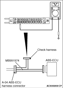
(1)Disconnect the ABS-ECU connector, connect special tool ABS check harness (MB991974) to
the harness-side connector, and then measure the voltage at the special tool connector side.
| note |
Do not connect the special tool ABS check harness (MB991974) to ABS-ECU.
|
(2)Turn the ignition switch to the ON position.
(3)Measure the voltage between the wheel speed sensor power supply terminal (signal
terminal) No.24 and the body earth, and between the wheel speed sensor earth terminal No.25
and the body earth.
OK: 1 volt or less
Q.
Is the check result normal?
Go to Step 6.
NO (Not normal at the terminal No.24 or 25) : Go to Step 7. : Go to Step 7.
|
|
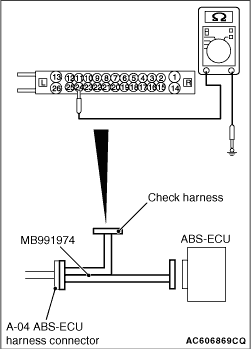
(1)Disconnect the ABS-ECU connector, connect special tool ABS check harness (MB991974) to
the harness-side connector, and then measure the resistance at the special tool connector side.
| note |
Do not connect the special tool ABS check harness (MB991974) to ABS-ECU.
|
(2)Resistance between the wheel speed sensor power supply terminal (signal terminal)
No.24 and body earth, and between the earth terminal No.25 and body earth.
OK: No continuity
Q.
Is the check result normal?
Go to Step 9.
NO (Not normal at the terminal No.24 or 25) : Go to Step 7.
|
|
|
Q.
Is the check result normal?
|
|
|
Repair the defective connector. Then go to Step 17.
|
|
|
|
|
|
- Check for short circuit in wheel speed sensor <RL> circuit
|
|
|
Q.
Is the check result normal?
|
|
|
Replace the wheel speed sensor <RL> (Refer to ). Then
go to Step 17.
|
|
|
|
|
|
Repair the wiring harness. Then go to Step 17.
|
|
|
|
|
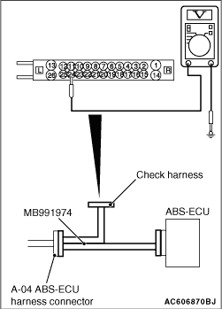
(1)Disconnect the ABS-ECU connector, connect special tool ABS check harness (MB991974) to
the ABS-ECU-side connector and harness-side connector, and then measure the voltage at the special
tool connector side.
(2)Turn the ignition switch to the ON position.
(3)Measure the voltage between the wheel speed sensor circuit power supply terminal
(signal terminal) No.24 and the body earth.
OK: Approximately battery voltage
Q.
Is the check result normal?
Go to Step 10.
Go to Step 12.
|
|
|
- Check for open circuit in wheel speed sensor <RL> circuit
|
|
|
Q.
Is the check result normal?
|
|
|
Repair the wiring harness. Then go to Step 17.
|
|
|
|
|
|
Q.
Is the check result normal?
|
|
|
Replace the wheel speed sensor <RL> (Refer to ). Then
go to Step 17.
|
|
|
|
|
|
Q.
Is the check result normal?
|
|
|
Repair the defective connector. Then go to Step 17.
|
|
|
|
|
|
Check how the wheel speed sensor <RL> is installed (Disconnection of
wheel speed sensor, loose mounting bolt, etc.).
|
|
|
Q.
Is the check result normal?
|
|
|
Reinstall the wheel speed sensor <RL> correctly (Refer to ).
Then go to Step 17.
|
|
|
|
|
|
Q.
Is the check result normal?
|
|
|
Replace the rear wheel hub assembly <RL> (Refer to GROUP 27A - Rear
axle hub assembly ).
|
|
|
|

|
Check the encoder for adhesion of foreign materials or deformation.
Q.
Is the check result normal?
Go to Step 16.
NO (Adhesion of foreign materials) : Remove the foreign materials and clean the encoder so as not to disturb the magnetization
pattern on it while taking care of the magnet, magnetic substance, and magnetic attraction.
NO (Deformation) : Replace the rear wheel hub assembly <RL> (Refer to GROUP 27A - Rear axle
hub assembly ).
|
|
|
(1)Erase the diagnosis code.
|
|
|
(2)Drive the vehicle at 20 km/h or more for more than 30 seconds.
| note |
The ABS warning lamp does not turn OFF in some cases unless the vehicle runs at 20 km/h
or higher.
|
|
|
|
Q.
Is the diagnosis code No.C1048 set?
|
|
|
Replace the hydraulic unit (ABS-ECU) (Refer to ). Then
go to Step 17.
|
|
|
|
|
|
This diagnosis is complete.
|
|
|
|
|
|
(1)Erase the diagnosis code.
|
|
|
(2)Drive the vehicle at 20 km/h or more for more than 30 seconds.
| note |
The ABS warning lamp does not turn OFF in some cases unless the vehicle runs at 20 km/h
or higher.
|
|
|
|
Q.
Is the diagnosis code No.C1048 set?
|
|
|
This diagnosis is complete.
|
|
|
|


