|
|
- ASC-ECU sends the illumination request signal of ASC OFF display to the combination
meter through ETACS-ECU via CAN communication.
- By the operation of ASC OFF switch, the ASC OFF display illuminates when the ASC
function is stopped.
- When the ASC OFF switch is pressed for 3 seconds or more, the ASC system turns OFF.
- When the ASC OFF switch is pressed for 15 seconds or more, the ASC is kept in ON
state and the system cannot be turned OFF until the ignition switch is turned to the ON position
next time.
|
|
|
This may be caused by faults in the CAN bus line, ETACS-ECU, combination meter or ASC-ECU.
|
|
|
- Damaged wiring harness and connectors
- Malfunction of ETACS-ECU
- Combination meter malfunction
- ASC-ECU malfunction
|
|
|
Use M.U.T.-III to diagnose the CAN bus lines.
|
|
|
Q.
Is the check result normal?
|
|
|
 Repair the CAN bus lines. (Refer to GROUP 54C - Troubleshooting Repair the CAN bus lines. (Refer to GROUP 54C - Troubleshooting  .)
Then go to Step 9. .)
Then go to Step 9.
|
|
|
|
|
|
Use M.U.T.-III to check the diagnosis code for the ASC system.
|
|
|
Q.
Is the diagnosis code set?
|
|
|
 Carry out the diagnosis for the diagnosis code. (Refer to .) Carry out the diagnosis for the diagnosis code. (Refer to .)
|
|
|
|
|
|
Q.
Is the check result normal?
|
|
|
Replace ASC OFF switch.(Refer to .) Then go to
Step 9.
|
|
|
|
|
|
Q.
Is the check result normal?
|
|
|
Repair the damaged connector.
|
|
|
|
|
|
- Check the power supply circuit for short circuit.
|
|
|
Q.
Is the check result normal?
|
|
|
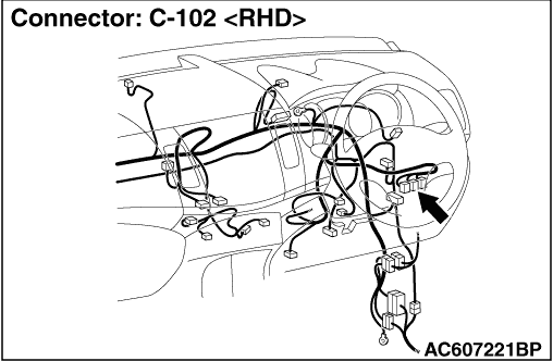
Repair the wiring harness between C-313 ETACS-ECU connector terminal No. 15 and
C-102 ASC OFF switch connector terminal No. 1.
|
|
|
|
|
|
Using M.U.T.-III, check that diagnosis code No. U0141 is set by the combination meter
system.
|
|
|
Q.
Is the diagnosis code set?
|
|
|
Diagnose the combination meter. (Refer to GROUP 54A - Combination Meter,
Troubleshooting .) Then go to Step 9.
|
|
|
|
|
|
Using M.U.T.-III, check that diagnosis code No. U0121 is set by the ETACS system.
|
|
|
Q.
Is the diagnosis code set?
|
|
|
Perform troubleshooting on ETACS-ECU. (Refer to GROUP 54A - ETACS, Troubleshooting .)
Then go to Step 8.
|
|
|
|
|
|
Q.
Does ASC OFF display turn ON and OFF normally?
|
|
|
Intermittent malfunction (Refer to GROUP 00 - How to Cope with Intermittent
Malfunction .)
|
|
|
|
|
|
Replace the hydraulic unit (integrated with ASC-ECU).(Refer to .) Then
go to Step 9.
|
|
|
|
|
|
Q.
Does ASC OFF display turn ON and OFF normally?
|
|
|
This diagnosis is complete.
|
|
|
|